Home
Fujitsu
Server
PRIMERGY RX2540 M2
Fujitsu PRIMERGY RX2540 M2
602 pages
Manual
To Next Page
To Next Page
To Previous Page
To Previous Page
Loading...
RX2540
M2
Upgrade and Maintenance Manual
411
Accessible drives
12.2.2.2
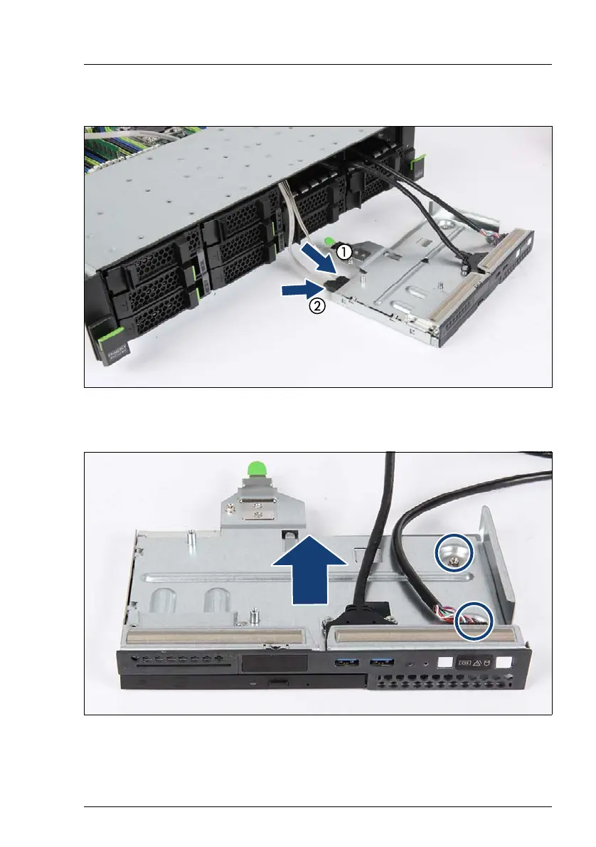
Rem
oving the ODD
Figure 293: Removing the ODD (A)
Ê
Disconnect the SA
T
A cable (2) and the power cable (1).
Figure 294: Removing the cover plate
Ê
Remove the two screws (see circles).
410
412
Table of Contents
Main Page
Contents
7
1 Introduction
29
1.1 Notational conventions
30
2 Before you start
31
2.1 Classification of procedures
33
2.1.1 Customer Replaceable Units (CRU)
33
2.1.2 Upgrade and Repair Units (URU)
34
2.1.3 Field Replaceable Units (FRU)
35
2.2 Average task duration
36
2.3 Tools you need at hand
37
2.4 Documents you need at hand
46
3 Important information
49
3.1 Safety instructions
49
3.2 ENERGY STAR
57
3.3 CE conformity
57
3.4 FCC Class A Compliance Statement
58
3.5 Environmental protection
59
4 Basic hardware procedures
61
4.1 Using diagnostics information
61
4.1.1 Locating the defective server
61
4.1.2 Determining the error class
62
4.1.2.1 Customer Self Service (CSS) indicator
62
4.1.2.2 Global Error indicator
62
4.1.3 Locating the defective component
63
4.1.3.1 Local diagnostic indicators on the front
63
4.1.3.2 Local diagnostic indicators on the system board
64
4.2 Shutting down the server
65
4.3 Disconnecting the power cord
66
4.4 Getting access to the component
68
4.4.1 Extending the server out of the rack
68
4.4.2 Removing the server from the rack
70
4.4.3 Removing the top cover
72
4.4.4 Removing the air duct
73
4.5 Reassembling
73
4.5.1 Installing the air duct
74
4.5.2 Installing the top cover
75
4.5.3 Mounting the server in the rack
76
4.5.4 Sliding the server into the rack
78
4.6 Connecting the power cord
79
4.7 Switching on the server
82
4.8 Handling riser modules
83
4.8.1 Riser modules for expansion cards (HL)
84
4.8.1.1 Removing the riser module 1 (HL)
84
4.8.1.2 Installing the riser module 1 (HL)
85
4.8.1.3 Removing the riser module 2 (HL)
87
4.8.1.4 Installing the riser module 2 (HL)
88
4.8.2 Riser modules for GPGPU cards (FL)
90
4.8.2.1 Installing the riser module 1 (FL)
90
4.8.2.2 Removing the riser module 1 (FL)
92
4.8.2.3 Installing the riser module 2 (FL)
92
4.8.2.4 Removing the riser module 2 (FL)
94
5 Basic software procedures
95
5.1 Starting the maintenance task
95
5.1.1 Suspending BitLocker functionality
95
5.1.2 Disabling SVOM boot watchdog functionality
96
5.1.2.1 Viewing boot watchdog settings
96
5.1.2.2 Configuring boot watchdog settings
97
5.1.3 Removing backup and optical disk media
99
5.1.4 Verifying and configuring the backup software solution
99
5.1.5 Note on server maintenance in a Multipath I/O environment
100
5.1.6 Switching on the ID indicator
102
5.2 Completing the maintenance task
103
5.2.1 Updating or recovering the system board BIOS and iRMC
103
5.2.1.1 Updating or recovering the system board BIOS
103
5.2.1.2 Updating or recovering the iRMC
104
5.2.2 Verifying system information backup / restore
105
5.2.3 Updating RAID controller firmware
106
5.2.4 Enabling Option ROM scan
107
5.2.5 Verifying and configuring the backup software solution
108
5.2.6 Resetting the boot retry counter
109
5.2.6.1 Viewing the boot retry counter
109
5.2.6.2 Resetting the boot retry counter
109
5.2.7 Resetting the error status after replacing memory modules or processors
111
5.2.7.1 Memory modules
111
5.2.7.2 Processors
112
5.2.8 Enabling SVOM boot watchdog functionality
114
5.2.9 Enabling replaced components in the system BIOS
115
5.2.10 Verifying the memory mode
115
5.2.11 Verifying the system time settings
116
5.2.12 Viewing and clearing the System Event Log (SEL)
117
5.2.12.1 Viewing the SEL
117
5.2.12.2 Clearing the SEL
118
5.2.13 Updating the NIC configuration file in a Linux and VMware environment
118
5.2.14 Resuming BitLocker functionality
120
5.2.15 Performing a RAID array rebuild
121
5.2.16 Looking up changed MAC / WWN addresses
122
5.2.16.1 Looking up MAC addresses
122
5.2.16.2 Looking up WWN addresses
122
5.2.17 Using the Chassis ID Prom Tool
123
5.2.18 Configuring LAN teaming
124
5.2.18.1 After replacing / upgrading LAN controllers
124
5.2.18.2 After replacing the system board
125
5.2.19 Switching off the ID indicator
125
5.2.20 Performing a fan test
126
6 Power supply unit (PSU)
129
6.1 Basic information
129
6.1.1 PSU configurations
130
6.1.2 Assembly rules
132
6.1.3 PSU bays
133
6.2 Installing hot-plug PSUs
133
6.2.1 Preliminary steps
133
6.2.2 Removing the dummy cover
134
6.2.3 Installing a hot-plug PSU
134
6.2.4 Concluding steps
135
6.3 Removing a hot-plug PSU
136
6.3.1 Preliminary steps
136
6.3.2 Note for servers using CMA (Cable Management Arm)
136
6.3.3 Removing a hot-plug PSU
138
6.3.4 Installing a dummy cover
139
6.3.5 Concluding steps
139
6.4 Replacing a hot-plug PSU
140
6.4.1 Preliminary steps
140
6.4.2 Note for servers using CMA (Cable Management Arm)
140
6.4.3 Removing the defective hot-plug PSU
141
6.4.4 Installing the new hot-plug PSU
141
6.4.5 Concluding steps
141
7 Hard disk drives (HDD) and solid state drives (SSD)
143
7.1 Basic information
144
7.2 3.5-inch cage configurations HDD/SSD
144
7.2.1 Mounting order for 3.5-inch HDDs
144
7.2.1.1 HDD mounting order for 4x 3.5-inch HDD configuration
145
7.2.1.2 HDD mounting order for 8x 3.5-inch HDD configurations
145
7.2.1.3 HDD mounting order for 12x 3.5-inch HDD configurations
146
7.2.2 Installing 3.5-inch HDD modules
147
7.2.2.1 Preliminary steps
147
7.2.2.2 Removing a 3.5-inch dummy module
148
7.2.2.3 Installing a 3.5-inch HDD module
149
7.2.2.4 Concluding steps
150
7.2.3 Removing 3.5-inch HDD modules
150
7.2.3.1 Preliminary steps
151
7.2.3.2 Removing a 3.5-inch HDD module
152
7.2.3.3 Installing a 3.5-inch dummy module
153
7.2.3.4 Concluding steps
153
7.2.4 Replacing a 3.5-inch HDD module
154
7.2.4.1 Preliminary steps
154
7.2.4.2 Removing a 3.5-inch HDD module
154
7.2.4.3 Installing a 3.5-inch HDD module
155
7.2.4.4 Concluding steps
155
7.2.5 2.5-inch HDDS/SSD in a 3.5-inch installation frame
155
7.2.5.1 Preliminary steps
155
7.2.5.2 Installing a 2.5-inch HDD/SSD into a 3.5-inch installation frame
155
7.2.5.3 Removing a 2.5-inch HDD/SSD out of a 3.5-inch installation frame
158
7.2.5.4 Concluding steps
159
7.3 Replacing 3.5-inch HDD/SSD SAS/SATA backplanes
160
7.3.1 Replacing the 4x 3.5-inch HDD SAS backplanes
160
7.3.1.1 Preliminary steps
160
7.3.1.2 Removing the 4x 3.5-inch SAS HDD backplane 1
161
7.3.1.3 Installing the 4x 3.5-inch HDD SAS backplane 1
163
7.3.1.4 Removing the 4x 3.5-inch SAS HDD backplane 2
166
7.3.1.5 Installing the 4x 3.5-inch HDD SAS backplane 2
167
7.3.1.6 Concluding steps
169
7.3.2 Upgrading SAS/SATA HDD backplane 2
170
7.3.2.1 Preliminary steps
170
7.3.2.2 Installing the 3.5-inch HDD backplane 2
170
7.3.2.3 Connecting the SAS cables
171
7.3.2.4 Concluding steps
172
7.3.3 Replacing the 12x 3.5-inch HDD backplane
173
7.3.3.1 Preliminary steps
173
7.3.3.2 Removing the SAS expander board
174
7.3.3.3 Removing the defective 12x 3.5-inch HDD backplane
175
7.3.3.4 Installing the new 12x 3.5-inch HDD backplane
176
7.3.3.5 Installing the SAS expander board
178
7.3.3.6 Concluding steps
179
7.3.4 Replacing the SAS expander board
180
7.3.4.1 Preliminary steps
180
7.3.4.2 Removing the SAS expander holder
180
7.3.4.3 Removing the defective SAS expander board
181
7.3.4.4 Installing the new SAS expander board
183
7.3.4.5 Installing the SAS expander board
184
7.3.4.6 Concluding steps
184
7.3.5 Replacing the connector card
185
7.3.5.1 Preliminary steps
185
7.3.5.2 Removing the SAS expander board
185
7.3.5.3 Removing the defective connector card
186
7.3.5.4 Installing the new connector card
186
7.3.5.5 Concluding steps
187
7.4 2.5-inch HDD/SSD configurations
187
7.4.1 Mounting order for 2.5-inch HDDs/SSDs
187
7.4.1.1 HDD mounting order for 8x 2.5-inch HDD/SSD configuration
188
7.4.1.2 HDD mounting order for 16x 2.5-inch HDD/SSD configuration
189
7.4.1.3 HDD mounting order for 24x 2.5-inch HDD/SSD configuration
190
7.4.1.4 HDD mounting order for additional 4x PCIe SSD SFFs accessible from the front side
191
7.4.1.5 HDD mounting order for 4x 2.5-inch SAS HDD/SSDs or PCIe SSDs accessible from the rear side
192
7.4.2 Installing 2.5-inch HDD/SSD modules
193
7.4.2.1 Preliminary steps
193
7.4.2.2 Removing a 2.5-inch dummy module
194
7.4.2.3 Installing a 2.5-inch HDD/SSD module
195
7.4.2.4 Concluding steps
196
7.4.3 Removing 2.5-inch HDD/SSD modules
197
7.4.3.1 Preliminary steps
197
7.4.3.2 Removing a 2.5-inch HDD/SSD module
198
7.4.3.3 Installing a 2.5-inch dummy module
199
7.4.3.4 Concluding steps
200
7.4.4 Replacing a 2.5-inch HDD/SSD module
200
7.4.4.1 Preliminary steps
200
7.4.4.2 Removing a 2.5-inch HDD/SSD module
201
7.4.4.3 Installing a 2.5-inch HDD/SSD module
201
7.4.4.4 Concluding steps
201
7.5 Replacing 2.5-inch HDD/SSD SAS/SATA backplanes
201
7.5.1 Replacing the 8x 2.5-inch HDD/SSD SAS backplane 1
201
7.5.1.1 Preliminary steps
201
7.5.1.2 Disconnecting cables from backplane
202
7.5.1.3 Removing the backplane
203
7.5.1.4 Installing the backplane
204
7.5.1.5 Connecting cables to backplane 1
205
7.5.1.6 Concluding steps
206
7.5.2 Replacing the 8x 2.5-inch HDD/SSD SAS backplane 2/3
207
7.5.2.1 Preliminary steps
207
7.5.2.2 Disconnecting cables from the backplane
208
7.5.2.3 Removing the backplane
208
7.5.2.4 Installing the backplane
208
7.5.2.5 Connecting cables to backplane 2/3
208
7.5.2.6 Concluding steps
210
7.5.3 Upgrading the 4x 2.5-inch PCIe SSD backplane (front side)
210
7.5.3.1 Preliminary steps
210
7.5.3.2 Installing the 4x 2.5-inch PCIe SSDbackplane
211
7.5.3.3 Connecting cables to PCIe backplane
212
7.5.3.4 Connecting cables to the PCIe switch
213
7.5.3.5 Concluding steps
214
7.5.4 Replacing the 4x 2.5-inch PCIe SSD backplane
214
7.5.4.1 Preliminary steps
214
7.5.4.2 Removing cables from PCIe backplane
215
7.5.4.3 Removing the 4x 2.5-inch PCIe SSD backplane
216
7.5.4.4 Installing the PCIe backplane
216
7.5.4.5 Concluding steps
216
7.5.5 Upgrading up to 24x 2.5-inch HDDs/SSDs
217
7.5.5.1 Preliminary steps
217
7.5.5.2 Installing the second/third SAS backplane
217
7.5.5.3 Concluding steps
218
7.5.6 Replacing the SAS expander board
218
7.5.6.1 Preliminary steps
218
7.5.6.2 Removing the SAS expander holder
219
7.5.6.3 Removing the SAS expander board
220
7.5.6.4 Installing the SAS expander board
220
7.5.6.5 Installing the SAS expander holder
221
7.5.6.6 Concluding steps
223
7.6 Rear HDD/SSD or PCIe SSD extension box
224
7.6.1 Replacing the backplane of the extension box
224
7.6.1.1 Preliminary steps
224
7.6.1.2 Disconnecting cables from the rear backplane
225
7.6.1.3 Removing the rear backplane
226
7.6.1.4 Installing the rear backplane
226
7.6.1.5 Connecting cables to the rear backplane
227
7.6.1.6 Concluding steps
228
7.6.2 Upgrading a rear extension box
229
7.6.2.1 Preliminary steps
229
7.6.2.2 Removing the rear air grid (left hand)
230
7.6.2.3 Installing the rear HDD cage
231
7.6.2.4 Installing the rear backplane
233
7.6.2.5 Connecting cables to the rear backplane
233
7.6.2.6 Concluding steps
234
7.6.3 Removing the rear extension box
235
7.6.3.1 Preliminary steps
235
7.6.3.2 Disconnecting cables from the rear backplane
235
7.6.3.3 Removing the rear HDD cage
236
7.6.3.4 Installing the rear air grid (left hand)
237
7.6.3.5 Concluding steps
238
8 Expansion cards and backup units
239
8.1 Basic information
240
8.1.1 Riser modules
241
8.1.1.1 Population rules
242
8.2 Handling slot brackets
243
8.2.1 Installing a slot bracket
243
8.2.1.1 Installing a standard slot bracket
243
8.2.1.2 Installing a slot bracket to the Network adapter D2755
245
8.2.1.3 Installing a slot bracket to the USB 3.0 interface card D3305
247
8.2.2 Removing a slot bracket
248
8.3 Handling SFP+ transceiver modules
249
8.3.1 Installing SFP+ transceiver modules
249
8.3.2 Removing an SFP+ transceiver module
252
8.3.3 Replacing SFP+ transceiver modules
254
8.4 Expansion cards
255
8.4.1 Installing expansion cards
255
8.4.1.1 Preliminary steps
255
8.4.1.2 Removing the slot cover
256
8.4.1.3 Installing an expansion card
256
8.4.1.4 Concluding steps
257
8.4.2 Removing expansion cards
258
8.4.2.1 Preliminary steps
258
8.4.2.2 Removing an expansion card
258
8.4.2.3 Installing a PCI slot cover
260
8.4.2.4 Concluding steps
260
8.4.3 Replacing expansion cards
261
8.4.3.1 Preliminary steps
261
8.4.3.2 Removing an expansion card
262
8.4.3.3 Installing an expansion card
262
8.4.3.4 Connecting cables to the expansion card
262
8.4.3.5 Connecting a battery backup unit to the expansion card
262
8.4.3.6 Concluding steps
262
8.5 Expansion cards in riser modules (HL)
263
8.5.1 Installing an expansion card in riser module 1
263
8.5.1.1 Preliminary steps
263
8.5.1.2 Installing a riser card
264
8.5.1.3 Installing a PCIe expansion card in a riser module
266
8.5.1.4 Removing the slot cover riser module 1
267
8.5.1.5 Removing the rear air grid riser module 1
268
8.5.1.6 Concluding steps
268
8.5.2 Removing an expansion card from riser module 1
269
8.5.2.1 Preliminary steps
269
8.5.2.2 Removing a PCIe expansion card from a riser module
270
8.5.2.3 Installing the slot cover riser module 1
270
8.5.2.4 Concluding steps
270
8.5.3 Installing an expansion card in riser module 2
271
8.5.3.1 Preliminary steps
271
8.5.3.2 Installing a riser card
271
8.5.3.3 Installing an expansion card in a riser module
271
8.5.3.4 Installing the air grid extension to riser module 2
272
8.5.3.5 Removing the rear air grid riser module 2
272
8.5.3.6 Removing the slot cover riser module 2
273
8.5.3.7 Concluding steps
273
8.5.4 Removing an expansion card from riser module 2
274
8.5.4.1 Preliminary steps
274
8.5.4.2 Removing the air grid extension from riser module 2
275
8.5.4.3 Removing the expansion card
275
8.5.4.4 Installing the slot cover riser module 2
276
8.5.4.5 Installing the rear air grid riser module 2
276
8.5.4.6 Concluding steps
277
8.5.5 Replacing expansion cards in riser modules
277
8.5.5.1 Preliminary steps
277
8.5.5.2 Removing the defective expansion card
278
8.5.5.3 Installing the new expansion card
278
8.5.5.4 Connecting cables to the expansion card
278
8.5.5.5 Connecting a battery backup unit to the expansion card
278
8.5.5.6 Concluding steps
279
8.5.6 Replacing a riser card
279
8.5.6.1 Preliminary steps
279
8.5.6.2 Removing the defective riser card
280
8.5.6.3 Installing the new riser card
281
8.5.6.4 Connecting cables to the expansion card
282
8.5.6.5 Connecting a battery backup unit to the expansion card
282
8.5.6.6 Concluding steps
282
8.6 GPGPU cards in riser modules (FL)
283
8.6.1 Installing a GPGPU card in riser module 1
283
8.6.1.1 Preliminary steps
283
8.6.1.2 Removing the slot cover from the riser card holder
284
8.6.1.3 Installing a riser card with one PCIe slot Gen3 x16
285
8.6.1.4 Installing a GPGPU card in a riser module
286
8.6.1.5 Replacing the heat sink (FL)
288
8.6.1.6 Removing the slot cover riser module 1
288
8.6.1.7 Removing the rear air grid riser module 1
288
8.6.1.8 Installing the riser module 1
289
8.6.1.9 Installing the FBU on the riser card holder
291
8.6.1.10 Installing the air duct riser module 1
292
8.6.1.11 Concluding steps
295
8.6.2 Removing a GPGPU card from riser module 1
296
8.6.2.1 Preliminary steps
296
8.6.2.2 Removing the FBU
297
8.6.2.3 Removing the riser module 1
297
8.6.2.4 Removing a GPGPU card (FL)
298
8.6.2.5 Installing the slot cover riser module 1
298
8.6.2.6 Installing the air duct
298
8.6.2.7 Concluding steps
299
8.6.3 Installing a GPGPU card in riser module 2
299
8.6.3.1 Preliminary steps
299
8.6.3.2 Removing the slot cover from the riser card holder
299
8.6.3.3 Installing a riser card
299
8.6.3.4 Installing a GPGPU card in a riser module
300
8.6.3.5 Installing the air grid extension to riser module 2
300
8.6.3.6 Replacing the heat sink (FL)
300
8.6.3.7 Removing the rear air grid riser module 2
300
8.6.3.8 Removing the slot cover riser module 2
301
8.6.3.9 Installing the riser module 2 (FL)
301
8.6.3.10 Installing the FBU riser module 2
302
8.6.3.11 Installing the air duct riser module 2
304
8.6.3.12 Concluding steps
306
8.6.4 Removing a GPGPU card in riser module 2
307
8.6.4.1 Preliminary steps
307
8.6.4.2 Removing the FBU
307
8.6.4.3 Removing the riser module 2
307
8.6.4.4 Removing the air grid extension from riser module 2 (FL)
308
8.6.4.5 Removing a GPGPU card
308
8.6.4.6 Installing the slot cover riser module 2
308
8.6.4.7 Installing the rear air grid riser module 2
308
8.6.4.8 Installing the air duct
308
8.6.4.9 Concluding steps
309
8.6.5 Replacing GPGPU cards in riser modules
309
8.6.5.1 Preliminary steps
309
8.6.5.2 Removing the defective GPGPU card
310
8.6.5.3 Installing the new GPGPU card
310
8.6.5.4 Connecting cables to the GPGPU card
310
8.6.5.5 Connecting a battery backup unit to the expansion card
310
8.6.5.6 Concluding steps
310
8.6.6 Replacing a riser card
311
8.6.6.1 Preliminary steps
311
8.6.6.2 Removing the defective GPGPU card
311
8.6.6.3 Installing the new GPGPU card
312
8.6.6.4 Connecting cables to the expansion cards
312
8.6.6.5 Connecting a battery backup unit to the expansion card
313
8.6.6.6 Concluding steps
313
8.7 Backup Units
314
8.7.1 Basic information
314
8.7.2 Installing an FBU
314
8.7.2.1 Preliminary steps
315
8.7.2.2 Installing TFM to the RAID controller
315
8.7.2.3 Preparing the FBU
318
8.7.2.4 Connecting the FBU to the RAID controller
318
8.7.2.5 Installing the FBU holder onto the air duct
319
8.7.2.6 Concluding steps
320
8.7.3 Removing an FBU
321
8.7.3.1 Preliminary steps
321
8.7.3.2 Removing the FBU holder from the air duct
322
8.7.3.3 Concluding steps
323
8.7.4 Replacing an FBU
324
8.7.4.1 Preliminary steps
324
8.7.4.2 Removing an FBU from the air duct
325
8.7.4.3 Disconnecting the FBU adapter cable from the FBU
325
8.7.4.4 Removing the FBU from the holder
326
8.7.4.5 Installing a new FBU
326
8.7.4.6 Concluding steps
326
8.8 DynamicLoM module
327
8.8.1 Basic information
327
8.8.1.1 PLAN EM 2x 1GB T
328
8.8.1.2 PLAN EM 4x 1GB T
329
8.8.1.3 PLAN EM 2x 10 GB SFP
330
8.8.1.4 PLAN EM 2x 10 GB T
331
8.8.2 Installing the DynamicLoM module
332
8.8.2.1 Preliminary steps
332
8.8.2.2 Removing the slot cover
332
8.8.2.3 Installing the DynamicLoM module
333
8.8.2.4 Concluding steps
334
8.8.2.5 Software configuration
335
8.8.3 Removing the DynamicLoM module
336
8.8.3.1 Preliminary steps
336
8.8.3.2 Removing the DynamicLoM module
337
8.8.3.3 Installing the slot cover
338
8.8.3.4 Concluding steps
339
8.8.4 Replacing the DynamicLoM module
339
8.8.4.1 Preliminary steps
339
8.8.4.2 Removing the DynamicLoM module
340
8.8.4.3 Installing the DynamicLoM module
340
8.8.4.4 Concluding steps
340
8.8.4.5 Software configuration
340
8.9 External COM1 connector
341
8.9.1 Installing the external COM1 connector
341
8.9.1.1 Preliminary steps
341
8.9.1.2 Breaking off the metal cover
342
8.9.1.3 Installing the COM1 connector
342
8.9.1.4 Concluding steps
344
8.9.2 Removing the external COM1 connector
344
8.9.2.1 Preliminary steps
344
8.9.2.2 Removing the COM1 connector
345
8.9.2.3 Concluding steps
346
8.9.3 Replacing the external COM1 connector
346
8.9.3.1 Preliminary steps
346
8.9.3.2 Removing the external COM1 connector
346
8.9.3.3 Installing the external COM1 connector
346
8.9.3.4 Concluding steps
346
9 Main memory
347
9.1 Basic information
348
9.1.1 Memory sequence
349
9.1.1.1 Population rules
349
9.1.1.2 Independant Channel mode
350
9.1.1.3 Mirrored and performance modes
351
9.1.1.4 Rank Sparing mode
352
9.2 Installing memory modules
356
9.2.1 Preliminary steps
356
9.2.2 Installing a memory module
357
9.2.3 Concluding steps
357
9.3 Removing memory modules
358
9.3.1 Preliminary steps
358
9.3.2 Removing a memory module
358
9.3.3 Concluding steps
359
9.4 Replacing memory modules
359
9.4.1 Preliminary steps
359
9.4.2 Removing the defective memory module
360
9.4.3 Installing a new memory module
360
9.4.4 Concluding steps
360
10 Processor (CPU)
361
10.1 Basic information
362
10.1.1 Supported CPUs
362
10.1.2 CPU locations
362
10.2 Installing CPUs
363
10.2.1 Preliminary steps
363
10.2.2 Installing the CPU
363
10.2.2.1 Opening the load plate
364
10.2.2.2 Installing the new CPU
368
10.2.2.3 Closing the load plate
370
10.2.3 Concluding steps
373
10.3 Removing CPUs
374
10.3.1 Preliminary steps
374
10.3.2 Removing a CPU
374
10.3.2.1 Opening the load plate
375
10.3.2.2 Closing the load plate
378
10.3.2.3 Installing the protective cover
379
10.3.2.4 Closing the load plate
380
10.3.3 Concluding steps
380
10.4 Upgrading or replacing CPUs
381
10.4.1 Preliminary steps
381
10.4.2 Upgrading or replacing a CPU
381
10.4.3 Concluding steps
382
10.5 Handling CPU heat sinks
383
10.5.1 Preliminary steps
383
10.5.2 Installing CPU heat sinks
383
10.5.2.1 Preparing the heat sink and CPU
385
10.5.2.2 Installing the heat sink
386
10.5.3 Removing CPU heat sinks
387
10.5.4 Replacing CPU heat sinks
388
10.5.4.1 Removing the CPU heat sink
388
10.5.4.2 Applying thermal paste
389
10.5.4.3 Installing the CPU heat sink
389
10.5.5 Concluding steps
389
10.6 Applying thermal paste
390
11 System fan
393
11.1 Basic information
393
11.1.1 Numbering of the fan modules
394
11.2 Replacing the system fan
395
11.2.1 Preliminary steps
395
11.2.2 Removing a system fan
395
11.2.3 Installing a system fan
396
11.2.4 Concluding steps
396
11.3 Replacing the fan box
397
11.3.1 Preliminary steps
397
11.3.2 Removing the fan box
397
11.3.3 Installing the fan box
399
11.3.4 Concluding steps
400
12 Accessible drives
401
12.1 Basic informations
402
12.2 Optical disk drive (ODD) for 3.5-inch version
403
12.2.1 Installing the ODD
403
12.2.1.1 Preliminary steps
403
12.2.1.2 Removing the ODD dummy cover
404
12.2.1.3 Installing an ODD
405
12.2.1.4 Concluding steps
409
12.2.2 Removing the ODD
410
12.2.2.1 Preliminary steps
410
12.2.2.2 Removing the ODD
411
12.2.2.3 Installing the ODD dummy module
413
12.2.2.4 Concluding steps
414
12.2.3 Replacing an ODD
414
12.2.3.1 Preliminary steps
414
12.2.3.2 Removing the defective ODD
414
12.2.3.3 Installing the new ODD
414
12.2.3.4 Concluding steps
415
12.3 ODD for 2.5-inch version
415
12.3.1 Installing the ODD
415
12.3.1.1 Preliminary steps
415
12.3.1.2 Removing the ODD dummy cover
416
12.3.1.3 Installing an ODD
417
12.3.1.4 Concluding steps
420
12.3.2 Removing the ODD
421
12.3.2.1 Preliminary steps
421
12.3.2.2 Removing the ODD
422
12.3.2.3 Installing the ODD dummy cover
424
12.3.2.4 Concluding steps
425
12.3.3 Replacing an optical disc drive (ODD)
425
12.3.3.1 Preliminary steps
425
12.3.3.2 Removing the defective ODD
425
12.3.3.3 Installing the new ODD
425
12.3.3.4 Concluding steps
426
12.4 LTO drive
426
12.4.1 Installing the LTO drive
426
12.4.1.1 Preliminary steps
426
12.4.1.2 Removing the air grid
427
12.4.1.3 Installing an LTO drive
428
12.4.1.4 Concluding steps
434
12.4.2 Removing the LTO drive
434
12.4.2.1 Preliminary steps
434
12.4.2.2 Removing the LTO drive
435
12.4.2.3 Concluding steps
440
12.4.3 Replacing a LTO drive
441
12.4.3.1 Preliminary steps
441
12.4.3.2 Removing the defective LTO drive
441
12.4.3.3 Installing the new LTO drive
441
12.4.3.4 Concluding steps
441
12.5 RDX drive
442
12.5.1 Installing the RDX drive
442
12.5.1.1 Preliminary steps
442
12.5.1.2 Preparing an RDX drive
443
12.5.1.3 Installing the front panel cage
444
12.5.1.4 Concluding steps
447
12.5.2 Removing the RDX drive
447
12.5.2.1 Preliminary steps
448
12.5.2.2 Removing the RDX drive
448
12.5.2.3 Concluding steps
450
12.5.3 Replacing a RDX drive
450
12.5.3.1 Preliminary steps
450
12.5.3.2 Removing the defective RDX drive
450
12.5.3.3 Installing the new RDX drive
451
12.5.3.4 Concluding steps
451
13 Front panel and external front connectors
453
13.1 Front panel module 3.5-inch versions
453
13.1.1 Replacing the front panel module
453
13.1.1.1 Preliminary steps
454
13.1.1.2 Removing the front panel module
455
13.1.1.3 Installing the front panel module
458
13.1.1.4 Concluding steps
462
13.2 Front panel board 3.5-inch versions
463
13.2.1 Replacing the front panel board
463
13.2.1.1 Preliminary steps
463
13.2.1.2 Removing the front panel module
464
13.2.1.3 Removing the front panel board
464
13.2.1.4 Installing the front panel board
465
13.2.1.5 Installing the front panel module
465
13.2.1.6 Concluding steps
465
13.3 Front VGA connector 3.5-inch versions
466
13.3.1 Installing the front VGA connector
466
13.3.1.1 Preliminary steps
466
13.3.1.2 Removing the front panel module
466
13.3.1.3 Preparing the front panel module
467
13.3.1.4 Installing the front VGA
468
13.3.1.5 Installing the front panel module
468
13.3.1.6 Concluding steps
469
13.3.2 Removing the front VGA connector
469
13.3.2.1 Preliminary steps
469
13.3.2.2 Removing the front panel module
469
13.3.2.3 Removing the front VGA cable
470
13.3.2.4 Installing the front panel module
471
13.3.2.5 Concluding steps
471
13.3.3 Replacing the front VGA connector
471
13.3.3.1 Preliminary steps
471
13.3.3.2 Removing the front panel module
471
13.3.3.3 Removing the front VGA connector
471
13.3.3.4 Installing the new front VGA connector
472
13.3.3.5 Installing the front panel module
472
13.3.3.6 Concluding steps
472
13.4 Front USB3.0 connector 3.5-inch versions
472
13.4.1 Installing the front USB3.0 connector
472
13.4.1.1 Preliminary steps
472
13.4.1.2 Removing the front panel module
473
13.4.1.3 Preparing the front USB3.0 connector
473
13.4.1.4 Installing the front USB3.0 connector
474
13.4.1.5 Installing the front panel module
474
13.4.1.6 Concluding steps
474
13.4.2 Removing the front USB3.0 connector
475
13.4.2.1 Preliminary steps
475
13.4.2.2 Removing the front panel module
475
13.4.2.3 Removing the front USB3.0 connector
476
13.4.2.4 Installing the front panel module
476
13.4.2.5 Concluding steps
476
13.4.3 Replacing the front USB3.0 connector
477
13.4.3.1 Preliminary steps
477
13.4.3.2 Removing the front panel module
477
13.4.3.3 Removing the front USB3.0 connector
477
13.4.3.4 Installing the new front USB3.0 connector
477
13.4.3.5 Installing the front panel module
477
13.4.3.6 Concluding steps
478
13.5 Front panel module 2.5-inch versions
478
13.5.1 Replacing the front panel module
478
13.5.1.1 Preliminary steps
479
13.5.1.2 Removing the front panel cage
479
13.5.1.3 Removing the front panel module
481
13.5.1.4 Installing the front panel module
483
13.5.1.5 Installing the front panel cage
485
13.5.1.6 Concluding steps
488
13.6 Front panel board 2.5-inch versions
489
13.6.1 Replacing the front panel board
489
13.6.1.1 Preliminary steps
489
13.6.1.2 Removing the front panel module
490
13.6.1.3 Removing the front panel board
490
13.6.1.4 Installing the front panel board
491
13.6.1.5 Installing front panel module
491
13.6.1.6 Concluding steps
491
13.7 Front VGA connector 2.5-inch versions
492
13.7.1 Installing the front VGA connector
492
13.7.1.1 Preliminary steps
492
13.7.1.2 Removing the front panel module
492
13.7.1.3 Preparing the front panel module
493
13.7.1.4 Installing the front VGA
493
13.7.1.5 Installing the front panel module
494
13.7.1.6 Concluding steps
494
13.7.2 Removing the front VGA connector
495
13.7.2.1 Preliminary steps
495
13.7.2.2 Removing the front panel module
495
13.7.2.3 Removing the front VGA cable
496
13.7.2.4 Installing the front panel module
497
13.7.2.5 Concluding steps
497
13.7.3 Replacing the front VGA connector
497
13.7.3.1 Preliminary steps
497
13.7.3.2 Removing the front panel module
497
13.7.3.3 Removing the front VGA connector
498
13.7.3.4 Installing the new front VGA connector
498
13.7.3.5 Installing the front panel module
498
13.7.3.6 Concluding steps
498
13.8 Front USB3.0 connector 2.5-inch versions
498
13.8.1 Installing the front USB3.0 connector
498
13.8.1.1 Preliminary steps
498
13.8.1.2 Removing the front panel module
499
13.8.1.3 Preparing the front USB3.0 connector
499
13.8.1.4 Installing the front USB3.0 connector
500
13.8.1.5 Installing the front panel module
501
13.8.1.6 Concluding steps
501
13.8.2 Removing the front USB3.0 connector
501
13.8.2.1 Preliminary steps
501
13.8.2.2 Removing the front panel module
501
13.8.2.3 Removing the front USB3.0 connector
502
13.8.2.4 Installing the front panel module
502
13.8.2.5 Concluding steps
502
13.8.3 Replacing the front USB3.0 connector
503
13.8.3.1 Preliminary steps
503
13.8.3.2 Removing the front panel module
503
13.8.3.3 Removing the front USB3.0 connector
503
13.8.3.4 Installing the new front USB3.0 connector
503
13.8.3.5 Installing the front panel module
503
13.8.3.6 Concluding steps
504
13.9 Front panel module on rack mounting bracket
504
13.9.1 Replacing the front panel module on RMB
504
13.9.1.1 Removing the front panel module from RMB
505
13.9.1.2 Installing the front panel module on RMB
506
13.9.1.3 Concluding steps
509
13.9.2 Replacing the ID card holder
510
13.9.2.1 Preliminary steps
510
13.9.2.2 Removing the ID card holder
510
13.9.2.3 Installing the ID card holder
512
13.9.2.4 Concluding steps
512
14 System board and components
513
14.1 Basic information
513
14.2 CMOS battery
514
14.2.1 Replacing the CMOS battery
514
14.2.1.1 Preliminary steps
514
14.2.1.2 Removing the battery
515
14.2.1.3 Installing the CMOS battery
516
14.2.1.4 Concluding steps
516
14.3 USB Flash Module (UFM)
517
14.3.1 Installing the UFM
517
14.3.1.1 Preliminary steps
517
14.3.1.2 Installing the UFM
518
14.3.1.3 Concluding steps
519
14.3.1.4 Software configuration
519
14.3.2 Removing the UFM
520
14.3.2.1 Preliminary steps
520
14.3.2.2 Removing the UFM
521
14.3.2.3 Concluding steps
521
14.3.3 Replacing the UFM
522
14.3.3.1 Preliminary steps
522
14.3.3.2 Removing the UFM
522
14.3.3.3 Installing the new UFM
524
14.3.3.4 Concluding steps
525
14.3.3.5 Software configuration
525
14.4 Trusted Platform Module (TPM)
526
14.4.1 Installing the TPM
526
14.4.1.1 Preliminary steps
526
14.4.1.2 Installing the TPM
527
14.4.1.3 Concluding steps
529
14.4.2 Removing the TPM
530
14.4.2.1 Preliminary steps
531
14.4.2.2 Removing the TPM
532
14.4.2.3 Concluding steps
534
14.4.3 Replacing the TPM
534
14.4.3.1 Preliminary steps
535
14.4.3.2 Removing the TPM
535
14.4.3.3 Installing the TPM
535
14.4.3.4 Concluding steps
536
14.5 SATA DOM
536
14.5.1 Installing the SATA DOM
536
14.5.1.1 Preliminary steps
536
14.5.1.2 Installing the SATA DOM
537
14.5.1.3 Concluding steps
538
14.5.2 Removing the SATA DOM
538
14.5.2.1 Preliminary steps
539
14.5.2.2 Removing the SATA DOM
539
14.5.2.3 Concluding steps
539
14.5.3 Replacing the SATA DOM
540
14.5.3.1 Preliminary steps
540
14.5.3.2 Replacing the SATA DOM
540
14.5.3.3 Concluding steps
540
14.6 iRMC microSD card
541
14.6.1 Installing the iRMC microSD card
541
14.6.1.1 Preliminary steps
541
14.6.1.2 Installing the iRMC microSD card
541
14.6.1.3 Concluding steps
542
14.6.2 Removing the iRMC microSD card
543
14.6.2.1 Preliminary steps
543
14.6.2.2 Removing the iRMC microSD card
543
14.6.2.3 Concluding steps
543
14.6.3 Replacing the iRMC microSD card
544
14.6.3.1 Preliminary steps
544
14.6.3.2 Replacing the iRMC microSD card
544
14.6.3.3 Concluding steps
545
14.7 System board
545
14.7.1 Replacing the system board
545
14.7.1.1 Preliminary steps
547
14.7.1.2 Removing the defective system board
549
14.7.1.3 Installing the system board
552
14.7.1.4 Concluding steps
555
15 Cables
559
15.1 List of used cables
559
15.2 Cabling plans
561
15.2.1 3.5-inch variants
562
15.2.1.1 Configuration 4x 3.5-inch HDD
562
15.2.1.2 Configuration 8x 3.5-inch HDD
564
15.2.1.3 Configuration 12x 3.5-inch HD
566
15.2.2 2.5-inch variants
567
15.2.2.1 Configuration 8x 2.5-inch HDD
567
15.2.2.2 Configuration 16x 2.5-inch HDD
568
15.2.2.3 Configuration 24x 2.5-inch HDD
570
15.2.2.4 Configuration 4x 2.5-inch PCIe SSD rear
571
15.2.2.5 Configuration 4x 2.5-inch SAS HDD/SSD rear
571
15.2.2.6 Configuration 4x 2.5-inch PCIe SSD front
572
15.2.2.7 Configuration 8x 2.5-inch HDD / 16x 2.5-inch HDD and LTO 4/5/6/7 drive
573
15.2.2.8 Configuration 8x 2.5-inch HDD / 16x 2.5-inch HDD and USB 3.0 RDX drive
574
15.2.2.9 Configuration GPGPU M60/P100
575
15.2.2.10 Configuration Quadro M4000
575
15.2.2.11 Configuration GRID K1/K2/M10
576
16 Appendix
577
16.1 Mechanical overview
577
16.1.1 Server front
577
16.1.1.1 3.5-inch HDD versions
577
16.1.1.2 2.5-inch HDD versions
578
16.1.2 Server rear
579
16.1.3 Server interior
580
16.2 Configuration tables
581
16.2.1 HDD/SSD mounting order
581
16.2.2 Memory board configuration table
581
16.2.3 Expansion card configuration table
581
16.3 Connectors and indicators
582
16.3.1 Connectors and indicators on the system board
582
16.3.1.1 Onboard connectors
582
16.3.1.2 Onboard indicators and controls
584
16.3.2 Server front
586
16.3.2.1 Indicators on the front panel
586
16.3.2.2 Indicators on the hot-plug HDD/SSD module
591
16.3.3 Server rear
592
16.3.3.1 Connectors on the I/O panel
592
16.3.3.2 I/O panel indicators
593
16.3.3.3 Indicators on PSUs (slide-in units)
597
16.4 Onboard settings
599
16.5 Minimum startup configuration
600
Related product manuals
Fujitsu PRIMERGY RX2540 M1
438 pages
Fujitsu PRIMERGY RX2540 M4
86 pages
Fujitsu PRIMERGY RX2540 M5
112 pages
Fujitsu PRIMERGY RX2540 M6
121 pages
Fujitsu PRIMERGY RX2540 M7
646 pages
Fujitsu PRIMERGY RX2510 M2
74 pages
Fujitsu PRIMERGY RX2560 M2
568 pages
Fujitsu PRIMERGY RX4770 M2
84 pages
Fujitsu PRIMERGY TX1330 M2
86 pages
Fujitsu D3320 PRIMERGY BX2560 M2
80 pages

 Loading...