592 Upgrade and Maintenance Manual RX2540 M2
16.3.3 Server rear
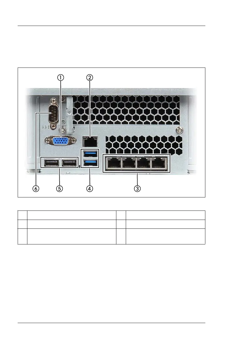
16.3.3.1 Connectors on the I/O panel
Figure 446: Connection panel on the rear
1 Video connector (blue) 4 2 USB connectors (USB 3.0)
2 Management LAN connector 5 2 USB connectors (USB 2.0)
3 DynamicLoM (optional, different
variants)*.
6 COM1 connector (optional)**
* The LAN connectors on the dynamicLoM modules are numbered in
ascending order from right to left beginning with “0”. The rightmost
connector (LAN 0) is the shared LAN connector respectively.
** The serial interface COM1 can be used as the standard interface or for
communication with iRMC.

 Loading...