4A
Fig. 4A-
23
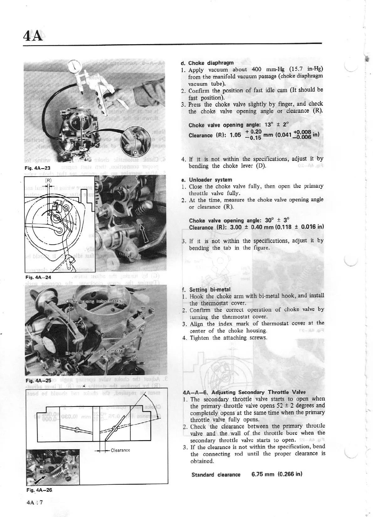
Fig.
4A-24
Fig.
4A-26
.
4A:
7
d. Choke diaphragm
1.
Apply vacuum about 400
mm-Hg (15.7 in-Hg)
from
the
manifold vacuum passage (choke diaphragm
va
cuum tube).
2. Confirm the position
of
fast idle cam (It should be
fast position).
3. Press the choke valve slightly
by
finger, and check
the choke
va
lve opening angle or clearance
(R)
.
Choke
valve
opening
angle: 13°
± 2°
Clearance
(R):
1.05
~g:~~
mm
(0
.041
~:~in)
4.
If
it
is
not
within the specifications, adjust
it
by
bending the choke lever (D).
e.
Unloader
system
1.
Close the choke
valve
fully, then open the primary
throttle valve fully.
2.
At the time, measure the choke valve opening angle
or
clearance (R).
Choke
val
ve
opening
angle:
30
°
±
3°
Clearance (R):
3.00
±
0.40
mm
(0.118
±
0.016
in)
3. If it
is
not within the specifications, adjust it
by
bending the tab in the figure.
f.
Setting bi-metal
1. Hook the choke arm with bi-metal hook, and install
the thermostat cover.
2. Confirm the correct operation
of
choke
valve
by
turning the thermostat cover.
3.
Align
the index mark of thermostat cover
at
the
center
of
the choke housing.
4. Tighten the attaching screws.
4A-A-6
. Adjusting Secondary Throttle Valve
1.
The secondary throttle
valve
starts
to
open when
the primary throttle valve opens 52
±
2 degrees and
completely opens at the same time when the primary
throttle valve
fully
opens.
2.
Check
the clearance between the primary
thr
ott
le
valve and the wall
of
the throttle bore when the
secondary throttle
valve
starts
to
open.
3.
If
the clearance
is
not
within the specification, bend
the connecting rod until the proper clearance
is
obtained.
Standard
clearance 6.
75
mm
(0.266 in)