II
Fig.
11-16
Fig. 11 -
17
Fig.
11-18
f ig.
11-19
11
:
5
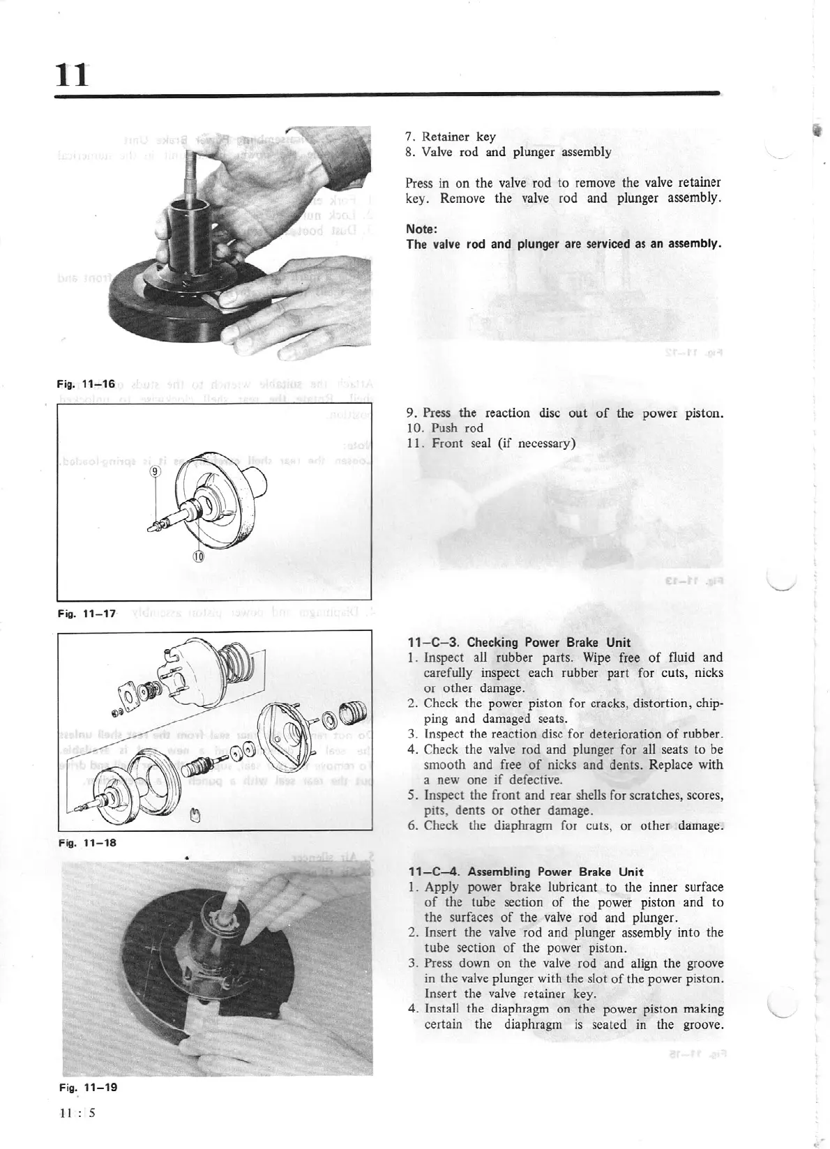
7. Retainer key
8. Valve rod and plunger assembly
Press in
on
the valve rod to remove the valve retainer
key. Remove the valve rod and plunger assembly.
Note:
The valve
rod and
plunger
are serviced as an
assembly.
9. Press the reaction
disc
out
of
the power piston.
IO.
Push rod
I
I.
Front seal
(if
necessary)
11
-
C-3.
Checking Power Brake
Unit
I. Inspect all rubber parts.
Wipe
free
of
fluid and
carefully inspect each rubber part for cuts, nicks
or
othe
r damage.
2. Check the power piston for cracks, distortion,
chip-
ping and damaged seats.
3. Inspect the reaction disc for deterioration
of
rubber.
4.
Check the valve rod and plunger for all seats to be
smooth and free
of
nicks and dents. Replace with
a new one
if
defective.
5.
Inspect the front and rear shells for scratches, scores,
pits, dents or other damage.
6. Check the diaphragm for cuts, or other damage.
11-C-4.
Assembling
Power Brake
Unit
I. Apply power brake lubricant
to
the inner surface
of
the tube section
of
the power piston and to
the surfaces
of
the valve rod and plunger.
2.
In
se
rt the valve rod and plunger assembly
into
the
tube section
of
the power piston.
3. Press down on the valve rod and align the groove
in
the
valve
plunger with the slot
of
the power piston.
Insert the valve retainer key.
4. Insta
ll
the diaphragm on the power piston making
certain the diaphragm
is
seated in the groove.