7B
Fig.
78
-
33
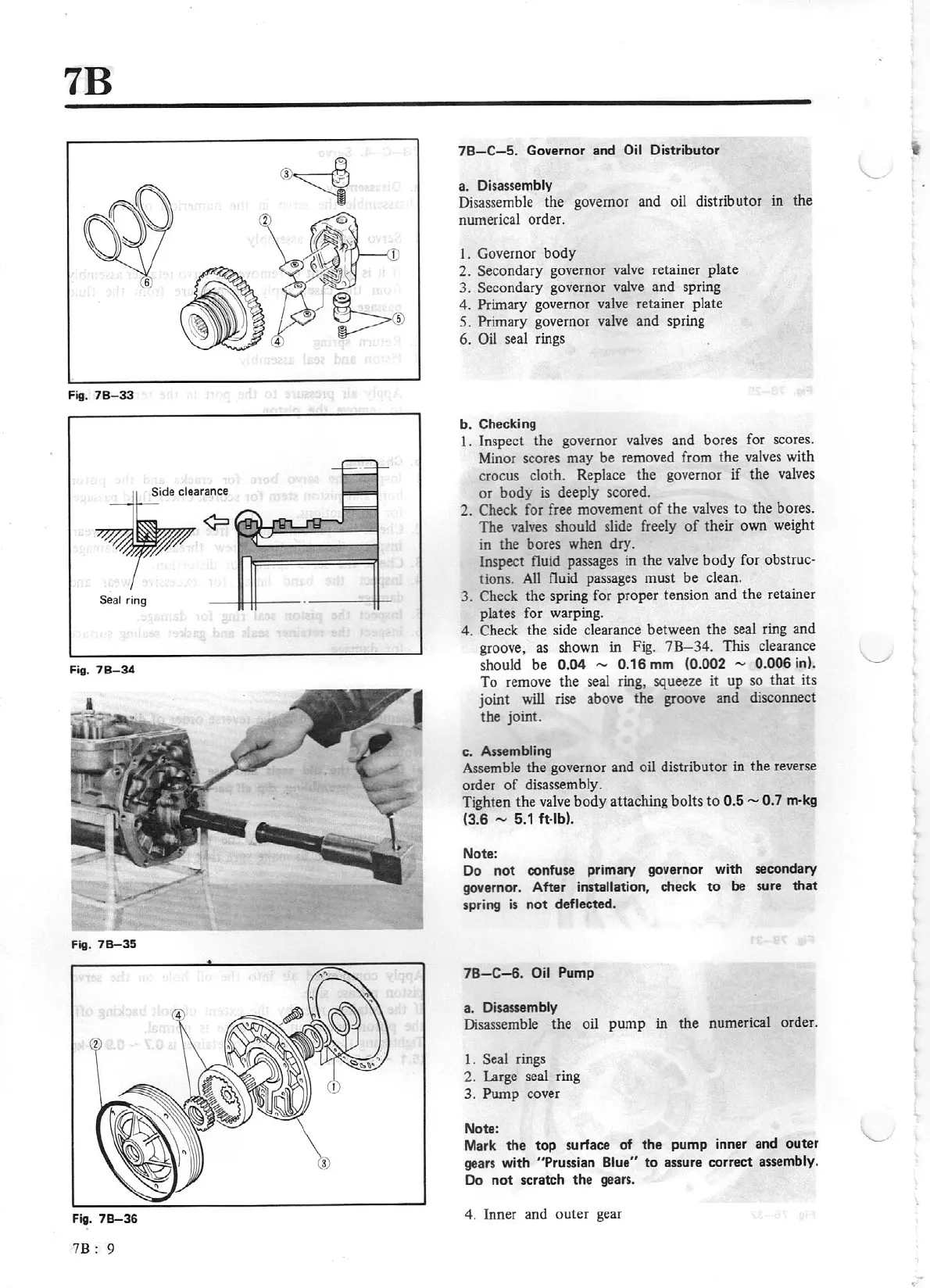
Side clearance
Seal
ring
Fig.
78-34
Fig.
78-35
Fig.
78-36
7
B:
9
7B-C
-5
. Governor and
Oil
Distributor
a.
Disassembly
Disassemble the governor and oil distributor
in
the
numerical order.
1.
Governor
body
2. Secondary governor
valve
retainer plate
3. Secondary governor valve and spring
4. Primary governor valve retainer plate
5.
Primary governor valve and spring
6.
Oil
seal rings
b.
Checking
1. Inspect the governor valves and bores for scores.
Minor scores may
be
removed from the
valves
with
crocus cloth. Replace the governor
if
the valves
or
body
is
deeply scored.
2. Check
for free movement
of
the
valves
to the bores.
The valves should slide freely
of
their own weight
in the bores when dry.
Inspect fluid passages
in
the valve
body
for
obstruc-
tions.
All
fluid passages must
be
clean.
3. Check the spring for proper tension and the retainer
plates for warping.
4. Check the side clearance between the seal ring and
groove,
as
shown in Fig.
7B-34.
This clearance
should be
0.04 - 0.16
mm
(0.002 - 0.006 in).
To remove the seal ring, squeeze it
up
so
that
its
joint
will
rise above the groove and disconnect
the joint.
c. Assembling
Assemble the governor and oil distributor in the reverse
order
of
disassembly.
Tighten the
valve
body
attaching bolts to
0.5 - 0.7
m-kg
(3.6
-
5.1
ft
-lb).
Note:
Do not confuse primary governor with secondary
governor. After installation,
check
to
be
sure
that
spring
is
not deflected.
78-C-6.
Oil
Pump
a.
Disassembly
Disassemble the oil pump in the numerical order.
1.
Seal rings
2. Large seal ring
3. Pump cover
Note:
Mark
the
top surface of
the
pump inner and outer
gears with
"Prussian Blue"
to
assure correct
assembly.
Do
not
scratch the gears.
4. Inner and outer gear