7B
Fig.
78-17
Fig.
78-18
Fig.
78-19
•
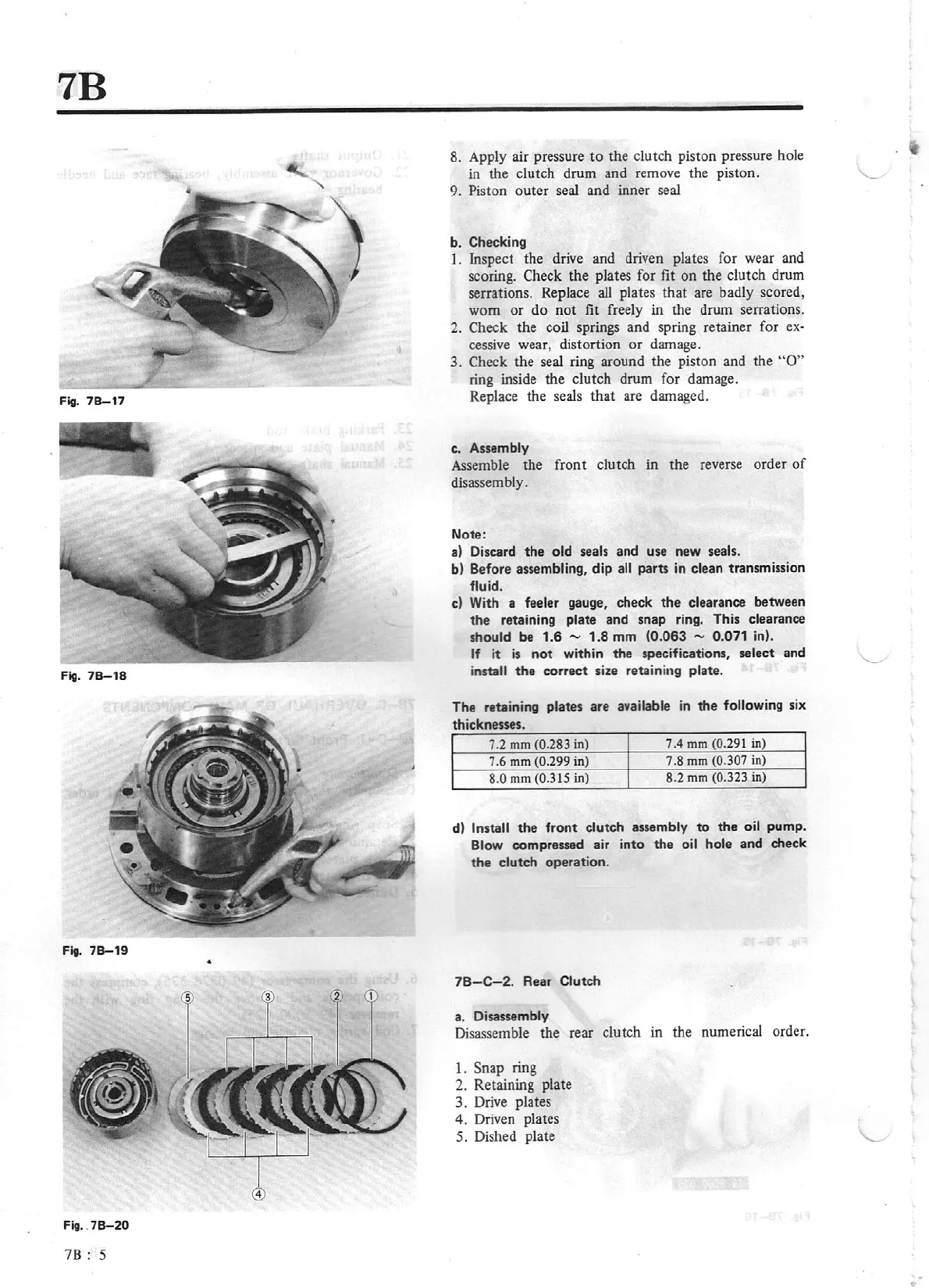
Fig.
78-20
78:
5
8. Apply air pressure
to
the clutch piston pressure hole
in the clutch drum and remove the piston.
\__
9. Piston outer
seal
and inner seal
b. Checking
1. Inspect the drive and driven plates for wear and
scoring. Check
th
e plates for fit
on
the clutch drum
serrations. Replace
all
plates
that
are badly scored,
worn
or
do
n
ot
fit freely in the drum serrations.
2. Check the coil springs and spring retainer for
ex·
cessive wear, distortion
or
damage.
3. Check the seal ring around the piston and the
"O"
ring inside the cl
ut
ch drum for damage.
Replace the
se
al
s that are damaged.
c. Assembly
Assemble the front cl
utch
in the reverse order
of
disassembly.
Note:
a)
Discard
the
old
sea
ls
and use new seals.
b) Before assembling, dip
all
parts in clean transmission
fluid.
c)
With a feeler gauge, check
the
clearance between
the
retaining plate and snap ring. This clearance
should be 1.6
-
1.8 mm
(0.063 - 0.071
in).
If
it
is
not
within the specifications, select and
install
the
correct size retaining plate.
The
retaining
plates are available
in
the
following six
thicknesses.
7.2
mm
(0.283
in)
7.4
mm
(0.291
in)
7.6
mm
(0.299
in)
7 .8
mm
(0.307
in)
8.0
mm
(0.315
in)
8.2
mm
(0.323
in)
d)
Install
the
front
clutch assembly
to
the
oil
pump.
Blow
compressed
air into the
oil hole and check
the
clutch operation.
78-C-2.
Rear Clutch
a. Disassembly
Disassemble the rear clutch in the numerical order.
1.
Snap
ring
2. Retaining plate
3. Drive plates
4. Driven plates
5. Dished plate
...