Flg.1A-37
Fig.
1A-38
i/Water
thermo
valve
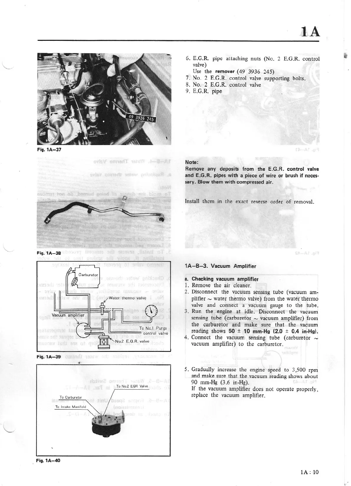
Fig.
1A-39
•
To
No.
2
ECl
A
Valve
To
CarbtXelOI
To
ln1
oko
M
orn
f
old
Fig.
1A-40
iA
6. E.G.R. pipe attaching nuts (No. 2 E.G.R. control
valve)
Use
the remover
(49
3936
245)
7.
No.
2
E.G.R. control valve supporting bolts.
8.
No.
2
E.G.R. control valve
9.
E.G.R. pipe
Note:
Remove any deposits from the E.G.R. control
valve
and E.G.R. pipes with a piece of wire or brush if
neces-
sary. Blow them with compres.sed air.
Install them
in
the exact reverse order
of
removal.
1A-B-3.
Vacuum
Amplifier
a. Checking vacuum amplifier
1. Remove the air cleaner.
2. Disconnect the vacuum sensing tube (vacuum
am-
plifier,....,
water thermo valve) from the water thermo
valve and connect a vacuum gauge
to
the tube.
3. Run the engine at idle. Disconnect the vacuum
se
nsing tube (carbur
etor
,....,
vacuum amplifier) from
the carburetor and make sure
that
the vacuum
reading shows
60
±
10
mm-Hg
(2.0 ±
0.4
in-Hg).
4. Connect the vacuum sensing tube (carburetor
vacuum amplifier)
to
the
carbur
eto
r.
5. Gradually increase the engine speed to 3
,
500
rpm
and make sure
that
the vacuum reading shows about
90
mm-Hg (3.6 in-Hg).
If
the vacuum amplifier does
not
operate properly,
replace the vacuum amplifier.
IA:
10