Fig.
78-60
Fig.
78-61
Fig.
78-62
7B
6.
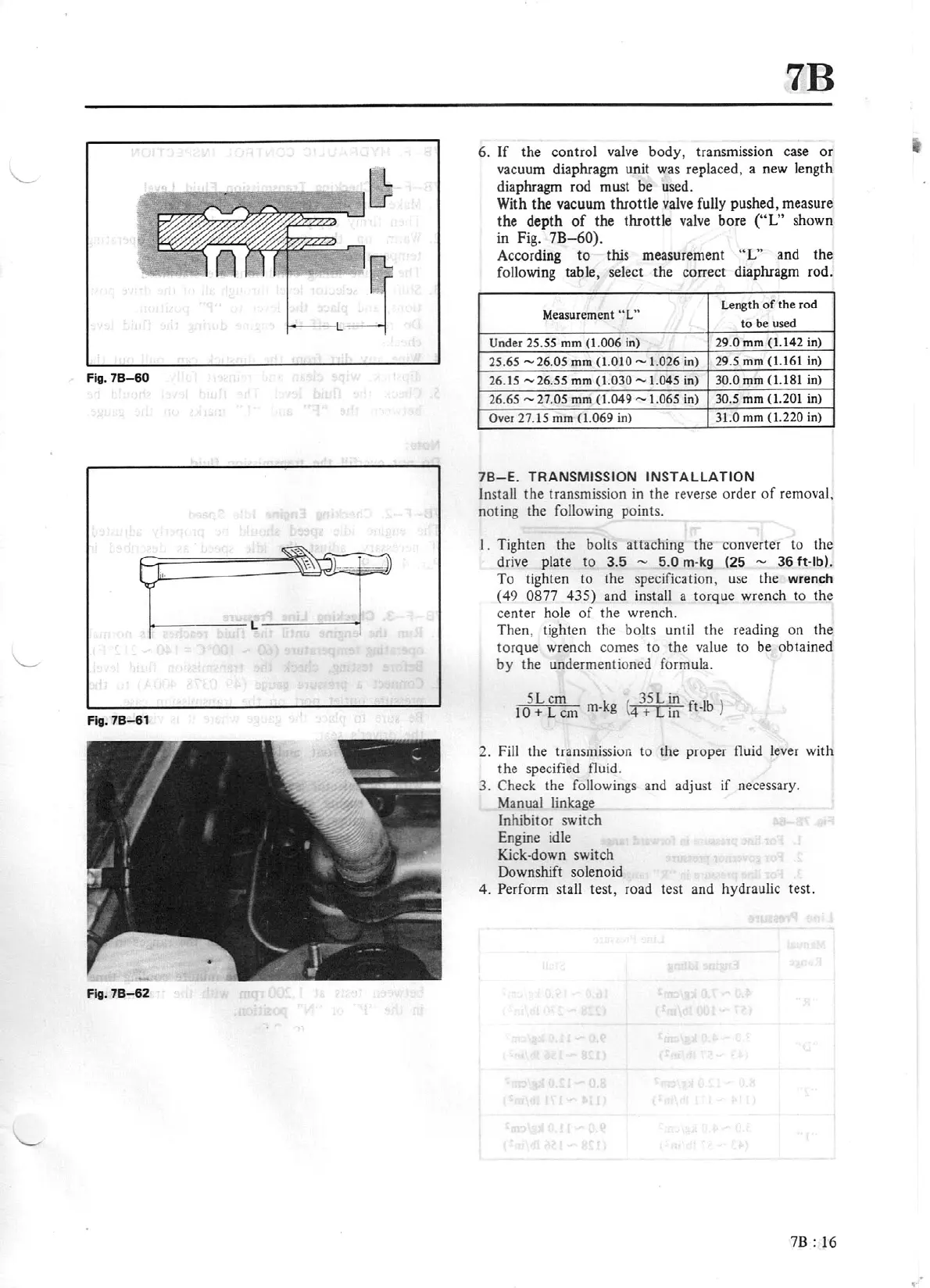
If
the control
valve
body,
transm1ss1on
case
or
vacuum diaphragm unit
was
replaced, a
new
length
diaphragm rod must be used.
With
the vacuum throttle
valve
fully pushed, measure
the depth
of
the throttle
valve
bo
re
("L"
shown
in
Fig.
7B-60).
According to this measurement
"L"
and the
followi
ng
table, select the correct diaphragm rod.
Measurement
"L"
Length
of
the rod
to be used
Under
25.55
mm
(1.006
in) 29.0
mm
(1.142 in)
25.65
-
26.05
mm
(1.010 -
1.026 in)
29.5
mm (1.161 in)
26.
15
-
26.55
mm (
1.030 -
1.045
in)
30.0 mm (1.181 in)
26.65
-
27.05
mm
(1.049 - 1.065
in)
30.5 mm
(1.201
in)
Over
27.15
mm
{1.069 in)
31.0
mm
(J.220
in)
78-E.
TRANSMISSION
INSTALLATION
Install the transmission
in
the reverse order
of
removal,
noting the following points.
I.
Tighten the
bolts
attaching the converter to the
drive plate to
3.5
- 5.0
m·
kg
(25
-
36
ft·lb).
To
tig
hten to the specification,
use
the wrench
(
49
0877
435)
and
in
stall a torque wrench to the
ce
nter hole
of
the wrench.
Then, tighten the bolts until the reading on the
torque wrench comes to the
value
to
be
obtained
by the undermentioned formula.
SL
cm
35Lin
)
10
+
L
cm
m-kg
(4
+
[in
ft-lb
2.
Fill
the transmission to the proper fluid
lever
with
the specified fluid .
3.
Check the followings and adjust if necessary.
Manual
linkage
Inhibitor switch
Engine
idle
Kick-down switch
Downshift solenoid
4.
Perform stall test, road test and hydraulic test.
7B:
16



 To Next Page