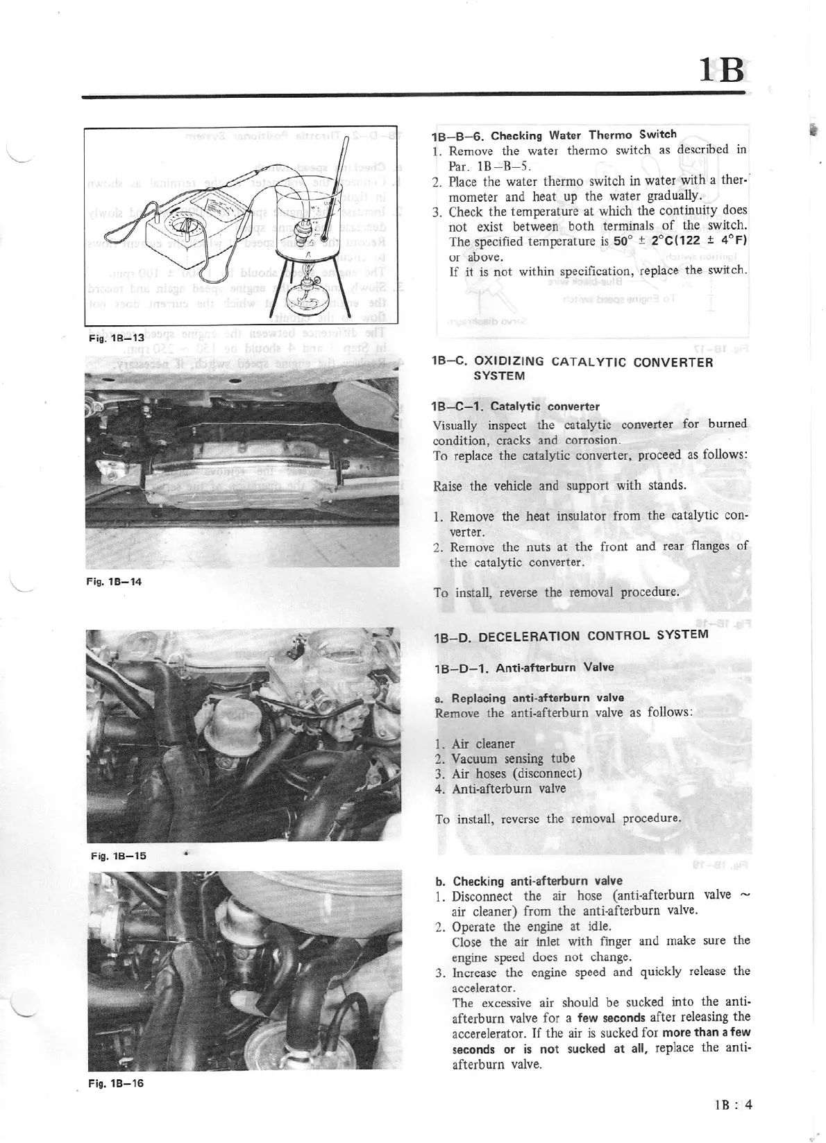
Fig.
18-13
Fig.
1B-14
Fig.
18-15
•
Fig.
1B-16
lB
1 B- B-
6.
Checking Water Thermo Switch
1.
Remove the water thermo switch as described in
Par.
lB
- B-
5.
2. Place the water thermo switch in water with a ther· ·
mometer and heat up the water gradually.
3.
Check the temperature at which
th
e continuity does
not exist between
both
termina
ls
of
the switch.
The specified
teonperature
is
50°
±
2°
C(122
±
4°
F)
or
above.
If
it
is
not
within specification, replace the switch.
1B-C.
OXIDIZING CATALYTIC
CONVERT
ER
SYSTEM
1 B-
C-1.
Catalytic converter
Visually inspect the catalytic convert
er
for burned
condition, cracks and corrosion.
To replace the catalytic converter, proceed
as
follows:
Raise the vehicle and support with stands.
1.
Re
move the heat insulator from the catalytic
con-
verter.
2. Remove the nuts at the front and rear fla
ng
es
of
the catalytic converter.
To install, reverse the removal procedure.
18-D.
DECELERATION CONTROL SYSTEM
1
B-D
- 1.
Anti·afterburn Valve
a. Replacing anti·afterburn valve
Remove the anti-afterburn valve as follows:
I .
Air
clean
er
2.
Vacuum
sensing tube
3.
Air
hoses (disconnect)
4.
Anti-afterburn valve
To install, reverse the removal procedure.
b. Checking
anti·afterburn valve
1.
Disconnect the
air
hose (anti-afterburn valve
air cleaner) from the anti·afterburn
valve.
2.
Op
erate
the engine at idle.
Close the
air
inlet with finger and make sure the
engine speed does
not
change.
3.
Increase
the engine speed and quickly release the
accelerator.
The excessive air should be sucked into the
anti·
afterburn valve for a few seconds after releasing the
accerelerator. If the
air
is
sucked for more
than
a
few
seconds or
is
not
sucked
at
all,
replace the
anti·
afterburn valve.
IB:
4