5
Fig.
5-38
Fig.
5-3
9
•
Fig.
5-40
5 :
11
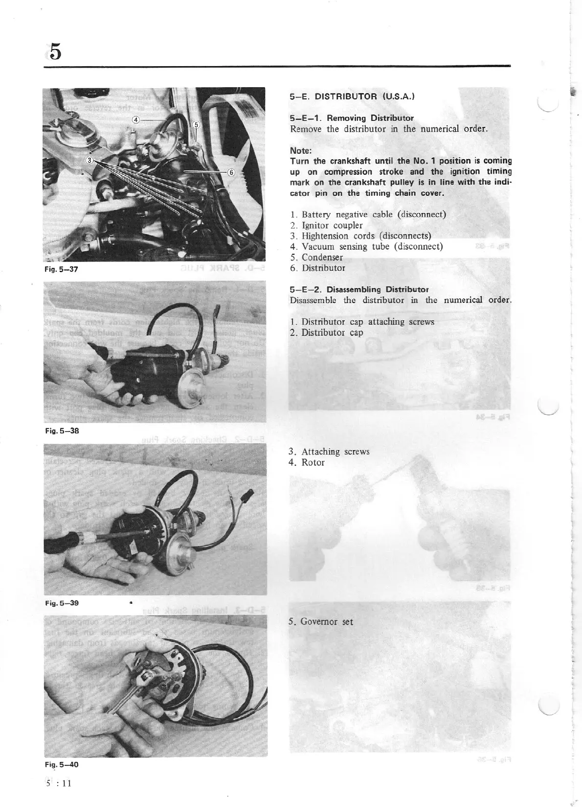
5- E.
DISTRIBUTOR (U.S.A.)
5
-E-1
.
Removing Distributor
Remove the distributor
in
the
numerical order.
Note:
Turn
the
crankshaft
until
the
No. 1 position
is
coming
up
on compression stroke and
the
ignition timing
mark on
the
crankshaft pulley
is
in
li
ne
with
the
indi-
cator pin on
the
timi
ng
chain cover.
1. Battery negative cable (disconnect)
2. Ignitor coupler
3.
rlightension cords (disconnects)
4.
Vacuum sensing tube (disconnect)
5.
Condenser
6. Distributor
5- E- 2.
Disas
se
mbling Distribu
tor
Disassemble the distributor
in the numerical order.
1. Distributor cap attaching screws
2.
Distribut
or
cap
3.
Attaching screws
4.
Rotor
5.
Governor set
 Loading...


