Fig
.
10
-
13
Fig
.
10
-
14
·
Flg
.
10-15
•
,.
.
Fig. 10-
16
10
10
-A
-3
. Disassembling
Steer
ing
Gear
Drain the lubricant and disassemble the steering gear
in the numerical order.
Hold the steering gear housing in a vise.
1.
Adjust screw lock
nut
2.
Side
cover
Remove the side cover by turning the adjusting screw
clockwise through the cover.
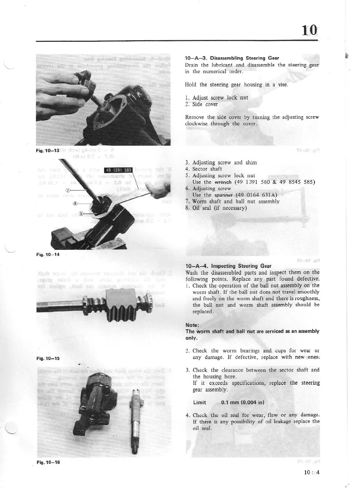
3.
Adjusting screw and shim
4. Sector shaft
5.
Adjusting screw lock
nut
Use
the wrench (49 1391
580
&
49
8545 585)
6. Adjusting screw
Use
the spanner
(49
0164
631A)
7.
Worm shaft and ball
nut
assembly
8.
Oil
seal
(if
necessary)
10-A-4
. Inspecting Steering G
ea
r
Wash
the disassembled parts and inspect them on the
following points. Replace any part found defective.
I.
Check the operation
of
the ball nut assembly
on
the
worm shaft.
If
the bail nut does
not
travel smoothly
and freely
on
the worm shaft and there
is
roughness,
the ball nut and worm shaft assembly should be
replaced.
Note:
The worm shaft and
ball
nut
are
se
rviced as an assembly
o
nl
y.
2.
Check
the worm bearings and cups for wear or
any damage.
1f
defective, replace with new ones.
3.
Check the clearance between the sector shaft and
the housing bore.
If
it exceeds specifications, replace the steering
gear assembly.
limit
0.1
mm
(0.004
in)
4.
Check
the oil seal for wear, flaw
or
any damage.
If
there is any possibility
of
oil leakage replace the
oil
seal.
10
:
4