7A
Fig.
7A-25
Fig. 7A- 26
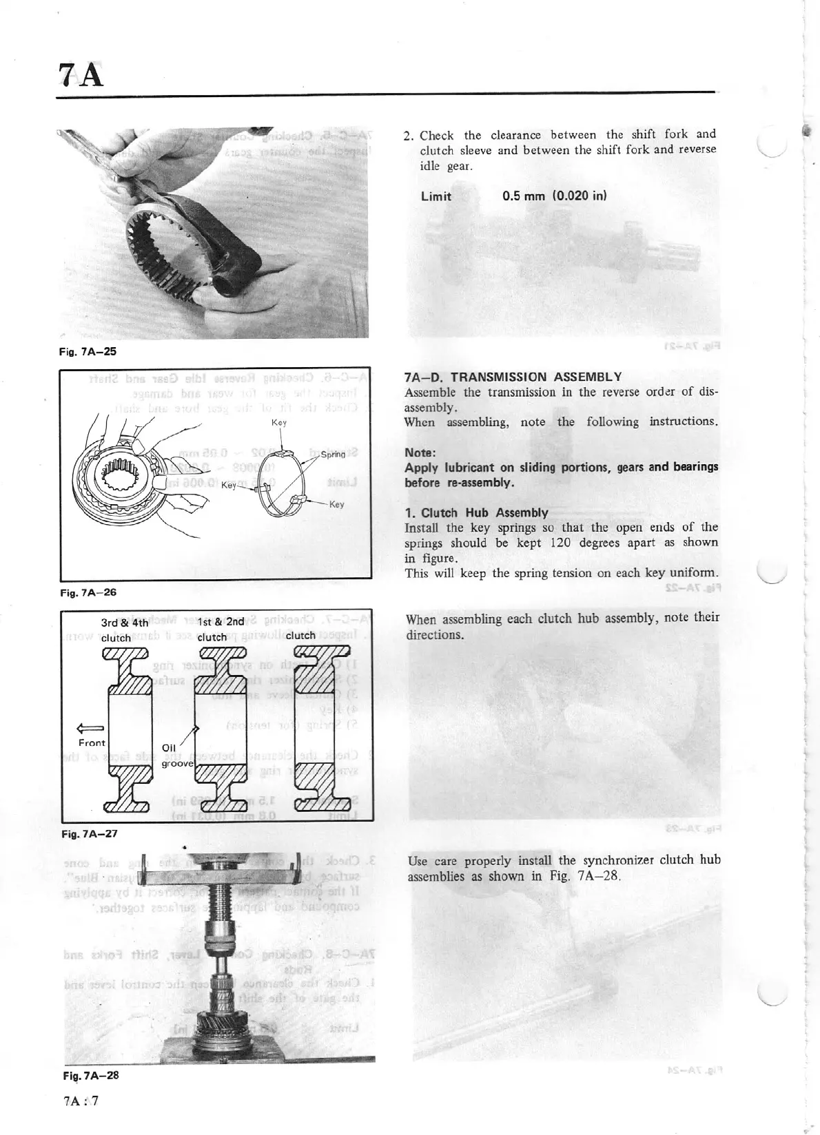
3rd
&
4
th
clutch
Fig.
7A-
27
Fig. 7A-
28
?A:
7
•
K
ey
1st
&
2nd
clutch
K
ey
clutch
2. Check the clearance b
et
ween the shift fork and
clutch sleeve and between the shift
fo
rk and reverse
idle gear.
Limit
0.5
mm
(0.
02
0 in)
7A - D.
TR
ANSMI
SS
ION ASSEMBLY
Assemble the transmission in the reverse
ord~r
of
dis-
assembly.
When
assembling,
note
the following instructions.
Note:
Apply
lu
brica
nt
on
sliding por
ti
ons,
gears and beari
ng
s
before r
e-
assembl
y.
1.
Cl
u
tc
h
Hub
Assembly
Install the key springs so that the open ends
of
the
springs should be
kept
120
degrees apart
as
shown
in figure.
This will keep the spring tension
on
each key uniform.
When assembling each clutch
hub
assembly, note their
directions.
Use
care properly install the synchronizer clutch hub
assemblies
as
shown in Fig. 7
A
-28.