13
Fig.
13-46
Fig.
13-47
Fi
g.
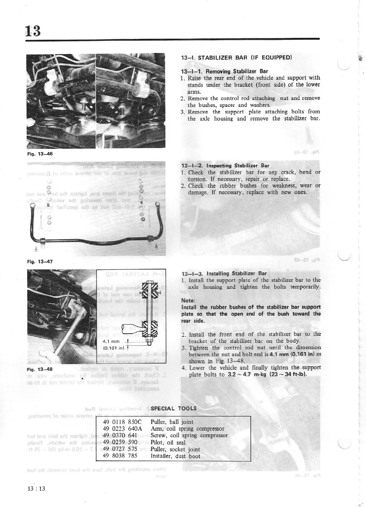
13-48
13
:
13
•
49
0118
85
0C
49
0223
640A
49
0370
641
49
025
9
590
49
0727
575
49
8038
785
13
-1.
STABILIZER
BAR
(IF
EQUIPPED)
13-1-1.
Removing
Stabilizer Bar
I.
Raise
the
rear end
of
the vehicle and support with
stands under the brack
et
(front side)
of
the lower
arms.
2. Remove the control rod attaching
nut
and remove
the bushes, spacer and washers.
3. Remove the support plate attaching bolts from
the
axle
housing and remove the stabilizer bar.
13-1-2.
Inspecting Stabilizer
Bar
I.
Check the stabilizer bar for any crack,
·bend
or
torsion.
If
necessary, repair
or
replace.
2. Check the rubber bushes for weakness, wear or
damage.
If
necessary, replace with new ones.
13-1-3.
Installing Stabilizer
Bar
1. Install
the
support plate
of
the stabilizer bar
to
the
axle housing and tighten the bolts temporarily.
Note:
Install
the
rubber bushes
of
the
stabilizer
bar
support
plate
so
that
the open end
of
the
bush toward
the
rear side.
2. Install the front end
of
the stabilizer bar
to
the
bracket
of
the stabilizer bar
on
the body.
3. Tighten the control rod
nut
until the dimension
between the
nut
and bolt end
is
4.1
mm
(0.161
in)
as
shown in Fig.
13-48.
4. Lower the vehicle and finally tighten
the
support
plate
bolts
to
3.2
-
4.7
m-kg
(23
-
34
ft-lb)
.
SPECIAL TOOLS
Puller, ball
joint
Arm, coil spring compressor
Screw, coil spri
ng
compressor
Pilot, oil seal
Puller,
socket
joint
Installer, dust
boot