Fig. 8 -
11
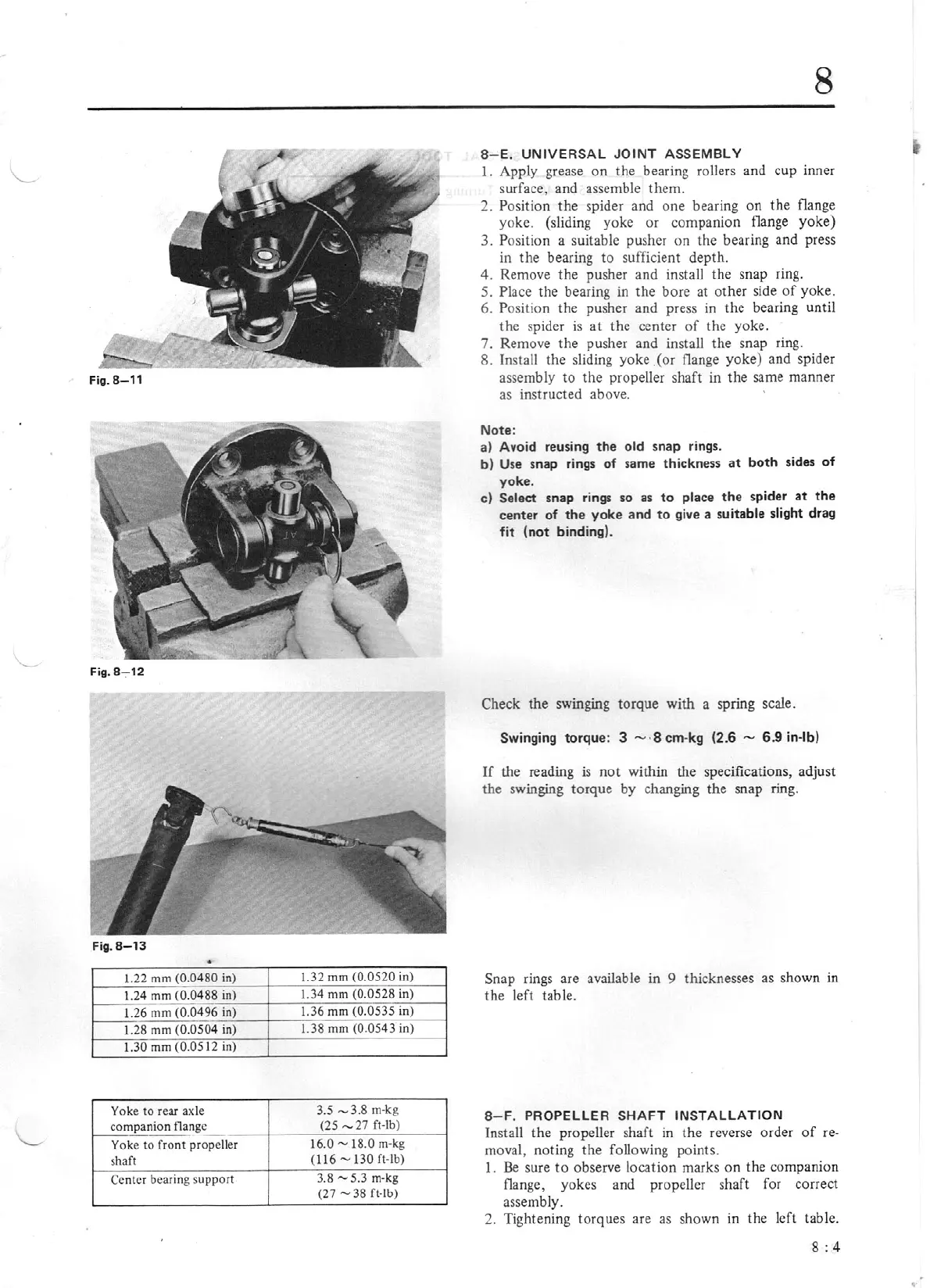
Fig. 8- 12
Fig.
8-13
•
1.22
mm
(0.0480
in)
l.32
mm
(0.0520
in)
l.24
mm
(0.0488
in)
1.34
mm
(0.0528
in)
.____
1.36
mm
(0.0535
in)
1.26
mm
(0.0496
in)
1.28
mm
(0
.0504
in)
1.38
mm
(0.0543
in)
1.30
mm
(0.0512
in)
Yoke
to
rear axle
3.5
-
3.8
m-kg
compa
nion flange
(25
-
27
ft-lb)
-
Yoke
to
front
propeller
16.0
-18.0
m-kg
shaft
(116
-1
30
ft-lb)
Ce
nter
bearing
support
3.8
-5.3
m-kg
(27
-38
ft-lb)
8
8-
E.
UNIV
ER
SAL
JO
INT ASSEMB
LY
1.
Apply grease on the bearing rollers and cup inner
surface, and assemble them.
2. Position
the
spider and
one
bearing
on
the
flange
yoke. (sliding yoke
or
companion flange
yoke)
3.
P
os
ition
a suitable pusher
on
the bearing and press
in
the
bearing
to
sufficient depth.
4. Remove
the
pusher and install the snap ring.
S.
Place
the bearing in the bore at
ot
her side
of
yoke.
6.
Position
the
pusher and press
in
the bearing until
the spider
is
at
the center
of
the yoke.
7. Remove the pusher and install
the
snap ring.
8.
Install the sliding yoke
(or
flange yoke) and spider
assembly
to
the propeller shaft
in
the
same manner
as
instructed above.
Note:
a) Avoid reusing the
old
snap
ri
ng
s.
b)
Use
snap
rings
of
same thickness
at
bo
th sides
of
yoke.
c)
Sel
ect
snap rin
gs
so as
to
place
the
spider
at
t he
cente
r
of
th
e yoke
and
to
gi
ve
a suitable slight
dr
ag
fit
(n
ot
binding).
Check the swinging torque with a spring scale.
Swingi
ng
torqu
e:
3
- ·8
cm-kg (2.6
-
6.9 in-lb)
If
the
reading
is
not
within the specifications, adjust
the swinging torque by changing
the
snap ring.
Snap
rings are available
in
9 thicknesses as shown
in
the
left table.
8- F. PROPELL
ER
SH
AFT
INSTA
LLATION
Install the propeller shaft
in
the reverse order
of
re-
moval, noting
the
following points.
1.
Be
sure
to
observe location marks
on
the companion
flange,
yokes and propeller
shaf
t for correct
assembly.
2. Tightening torques are as shown
in
the
left table.
8:4