5
Fig.
5
-6
Fi
g.
5-7
Fig.
5- 8
Fig.
5- 9
5 :
3
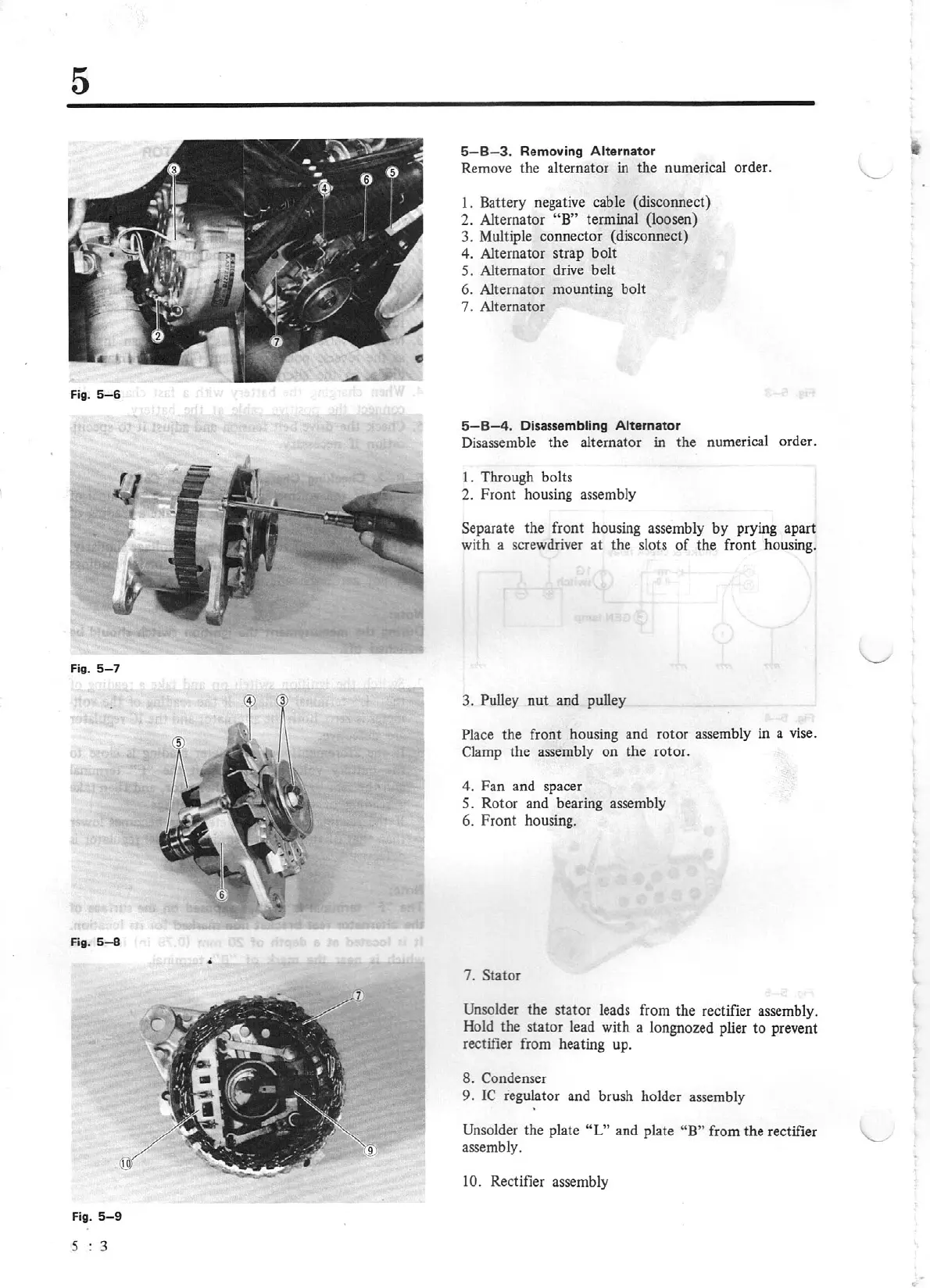
5-8-3.
Removing
Alterna
to
r
Remove the alternator in the numerical order.
1.
Battery negat
iv
e
cab
le (disconnect)
2. Alternator "B"
terminal (loosen)
3. Multiple connector (disconnect)
4. Alternator strap bolt
5. Alternator drive belt
6. Alternator mounting bolt
7. Alternator
5-8
-4
.
Disassembling
Alternator
Disassemble the alternator in the numerical order.
I
.
Through bolts
2.
Front housing assembly
Separate the front housing assembly
by
prying apart
wi
th a screwdriver
at
the slots
of
the front housing.
3. Pulley nut and pulley
Pla
ce
the front housing and rotor assembly in
a
vis
e.
Clamp the
ass
embly on the rotor.
4.
Fan
and spacer
5. Rotor and bearing assembly
6. Front housing.
7. Stator
Unsolder the stator leads from the rectifier
asse
mbly.
Hold the stator lead with a longnozed plier
to
prevent
rectifier from heating up.
8. Condenser
9. IC regulator and brush holder assembly
Unsolder
the plate
"L"
and plate
"B"
from
th
e rectifier
assembly.
10.
Rectifier assembly