1
Fig.
1-44
Fig,
1-47
l :
13
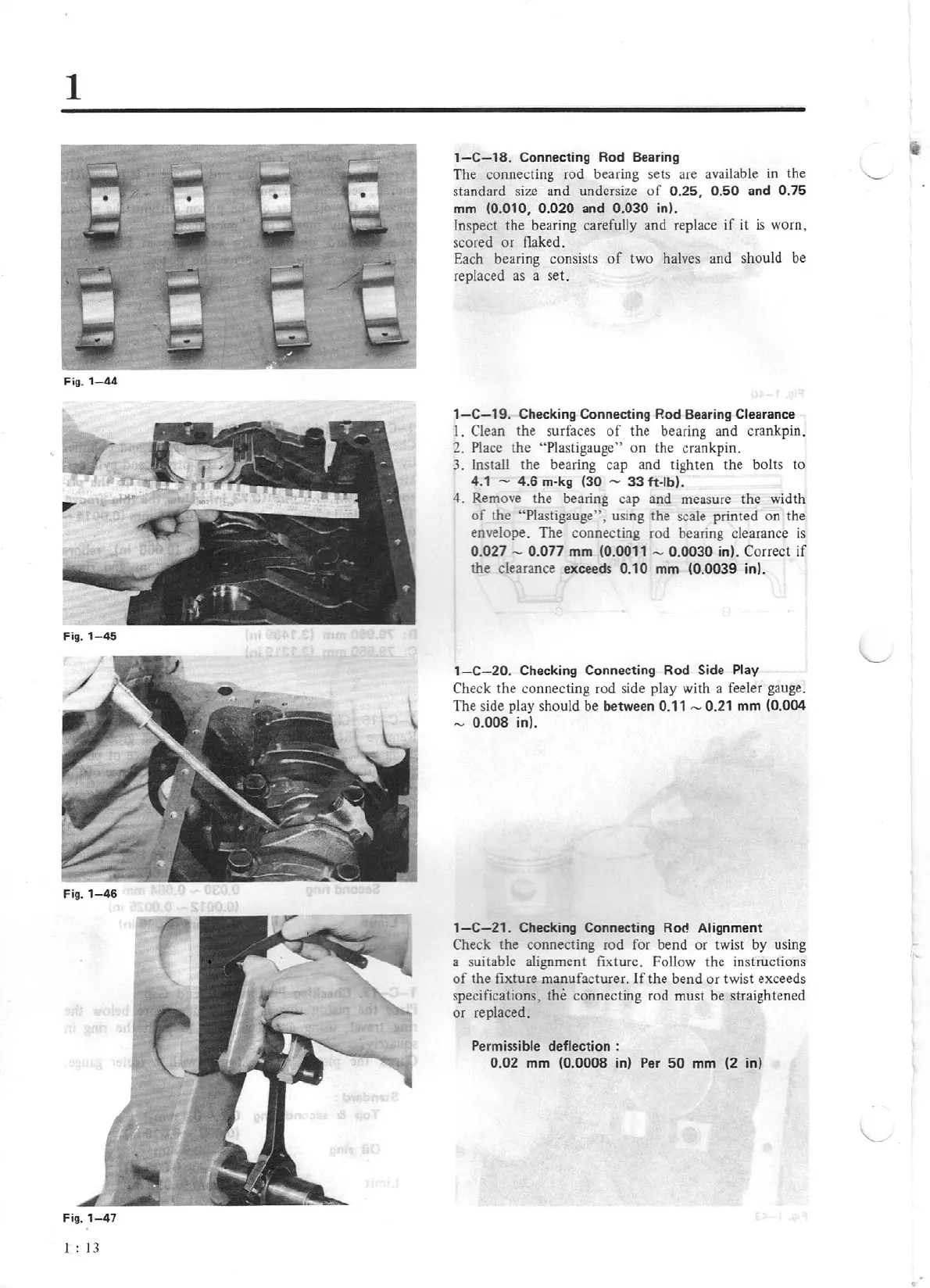
1-C-18
. Connecting Rod Bearing
The connecting rod bearing sets are available
in
the
standard size and undersize
of
0.25, 0.50 and 0.75
mm (0.010, 0.020 and 0.030 in).
Inspect the bear
in
g carefully and replace
if
it
is
worn,
scored or flaked .
Each bearing consists
of
two halves and should be
replaced
as
a set.
1-C-19
. Checking Connecting Rod Bearing Clearance
1.
Clean the surfaces
of
the bearing and crankpin.
2. Place the "Plasti
ga
ug
e"
on the crankpin.
3. Install the bearing cap and tighten the bolts to
4.1 - 4.6 m-kg (30 -
33
ft-lb).
4.
Remove the bearing cap and measure the width
of
the "Plastigauge", using the scale printed on the
envelope. The connecting rod bearing clearance
is
0.027 - 0.077 mm (0.0011 - 0.0030 in). Correct
if
the clearance exceeds 0
.1
0 mm (0.0039 in).
1-C-20
. Checking Connecting Rod Side Play
Check the connecting rod side play with a feeler gauge.
The side play should be between 0.11 - 0.21 mm (0.004
- 0.008 in).
1-C-21.
Checking Connecting Rod Alignme
nt
Check the connecting rod for bend or twist by using
a suitable alignment fixture. Follow the instructions
of
the fixture manufacturer. If the bend or twist exceeds
specificatio
ns
, the connecting rod must be straightened
or replaced.
Permissible deflection :
0.02 mm (0.0008 in) Per
50
mm
(2
in)
..