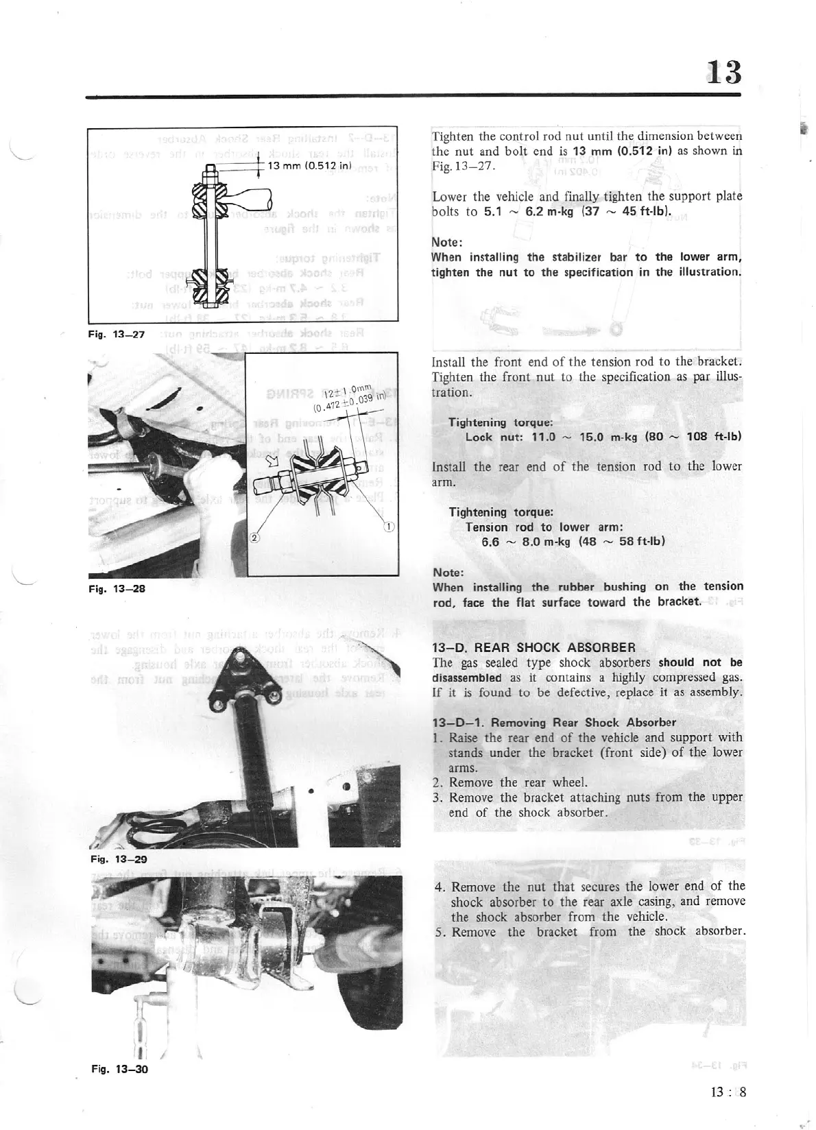
Fig.
13
-
27
Fig.
13-28
•
I
Fig.
13
-30
13
Tighten
the
control rod
nut
until the dimension between
the
nut
and
bolt
end
is
13
mm
(0.
512
in) as shown in
Fig.13-27.
Lower the vehicle and finally tighten t
he
support plate
bolts
to
5.1
,._
6.2
m-kg
(37
,._
45
ft-lb).
Note:
When
installing
the
stabilizer bar
to
the
lower arm,
tighten
the
nut
to
the
specification
in
the
illustr
at
ion.
Install the front end
of
the
tension rod
to
the bracket.
Tighten the front
nut
to the specification as par
illus-
tration.
Tightening torque:
Lock
nut
:
11
.0 -
15
.0
m-kg
(80
.....,
108
ft
-lb)
in
stall
the
rear end
of
the
tension rod to the lower
arm.
Tightening torque:
Tension rod
to
lower arm:
6.6 -
8.0
m-kg
(48
.....,
58
ft-lb)
Note:
When
installing
the
rubber bushi
ng
on
the
tension
rod, face
the
flat
surface toward the bracket.
13-D.
REAR SHOCK ABSORBER
The gas sealed
type
shock absorbers should
not
be
disassembled as it contains a highly compressed gas.
If
it
is
found
to
be defective, replace
it
as assemb
ly
.
13-0
- 1.
Removing Rear Shock Absorber
I.
Raise
the
rear end
of
the
vehicle and support with
stands under the bracket (front side)
of
the
lower
arms.
2. Remove
the
rear wheel.
3.
Remove the bracket attaching nuts from
the
upper
end
of
the
shock absorber.
4. Remove the nut that secures the lower end
of
the
shock absorber
to
the
rear axle casing, and remove
the
shock absorber from
the
vehicle.
5.
Remove
the
bracket from
the
shock absorber.
13
: 8