14
Fig.
14
-
66
Fig.
14-66
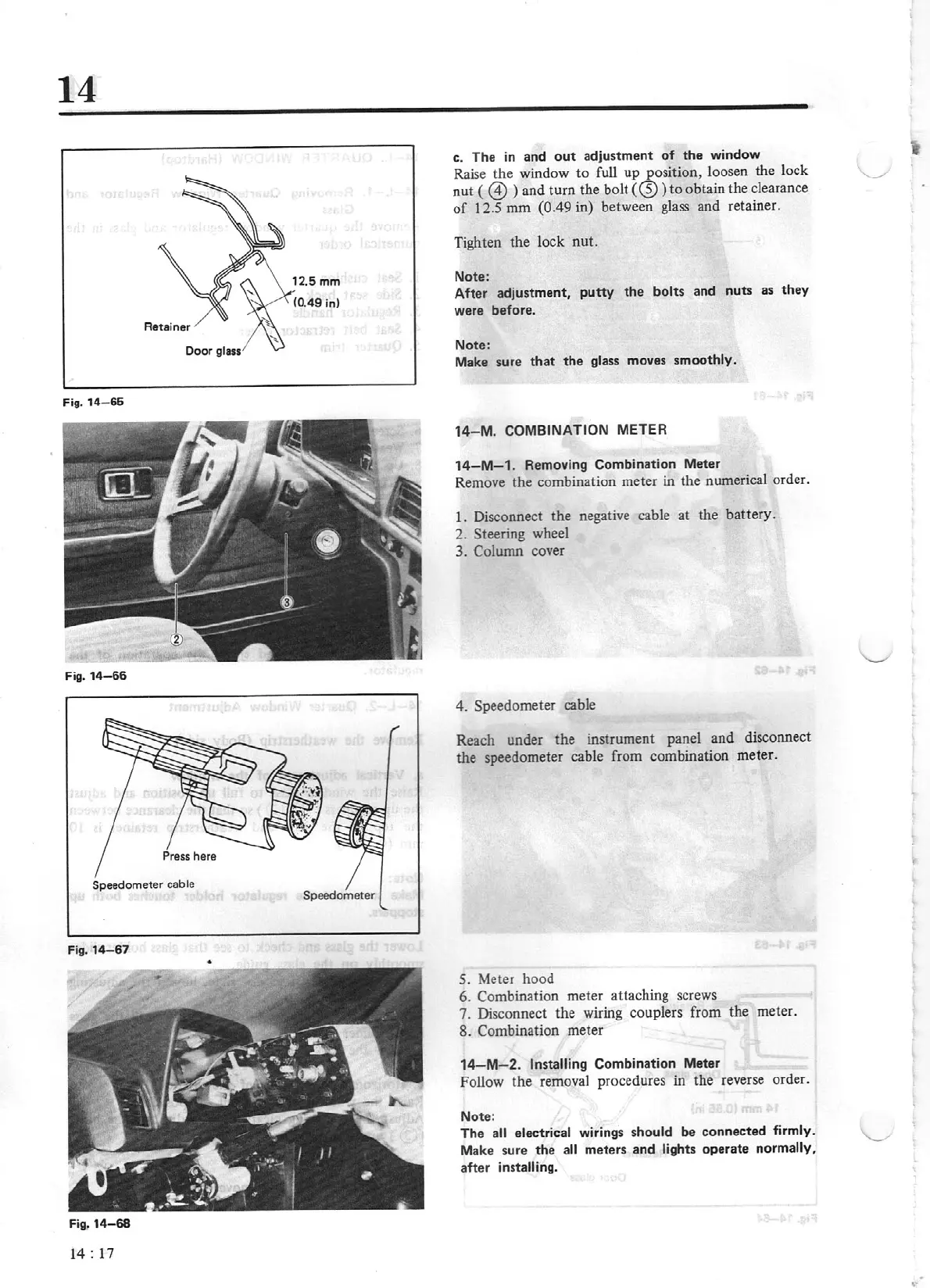
Speedometer
cable
Speedometer
Fig.
14-87
Fig.
14-68
1
4:
17
c.
Th
e in and
out
adjustment
of
the
window
Raise the window to full
up
,..e_osit
ion, loosen the lock
nut (
@ )
and turn the bolt (
<2))
to
obtain
Lhe
clearance
of
12.S
mm
{0.49
in)
between
glass
and retainer.
Tighten the Jock nut.
No
te:
Aft
er
adjustment
,
putty
t
he
bolts
and
nuts
as
th
ey
ware before.
Note:
Make s
ur
e
that
the
glass
moves
s
moothly
.
14
- M.
COMBINATION
ME
TE
R
14-M-1.
Removing Combination Meter
Remove the combination meter in the numerical order.
1.
Disconnect the negative cable at the
batt
ery.
2. Steering wheel
3. Column cover
4. Speedometer cable
Reach under the instrument panel and disconnect
the speedometer cable from combination meter.
S.
Meter hood
6. Combination meter attaching screws
7. Disconnect the wiring couplers from the meter.
8. Combination meter
14
- M- 2. Installing
Combination Meter
Follow the removal procedures in
th
e reverse order.
No
te
:
Th
e
a
ll
electrical
wmng
s
s
hould
be
connected
firmly.
Make s
ure
the
a
ll
meters
and
lights
operate
normally,
after installing.