Fig,
10A-2
3
Fig.
10A-24
r
"'
Fig.
10A-25
Fig.
10A
- 28
lOA
8. T
um
the stub shaft
to
center the piston.
9.
Thread the side cover
on
the adjusting screw
of
the sect
or
shaft until
it
bott
oms, then loosen
it
one
and one-half turns.
10.
Apply Vaseline to the
se
ctor shaft bearing and
journal.
Install
the sector shaft so the center gear
tooth
meshes with the center groove in the rack-
piston.
Be
sure the cover 0-ring is in place before
pushing the cover down
on
the housing.
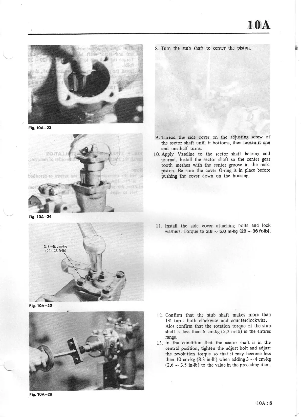
I I .
install the side cover
atta
ching bolts and lock
washers. Torque
to
3.8
....,
5.0
m-kg
(29
-
36
ft
-
lb
).
12. Confirm that the stub shaft makes more than
1
% turns bo
th
clockwise and counterclockwise.
Ales confinn that the rotation torque
of
the stub
shaft
is
less
than 6 cm-kg
(5
.2
in-lb) in the entires
range.
13. In the condition that the sector shaft
is
in the
central position, tighten the adjust bolt and adjust
the revolution torque so that
it
may become less
than l
0
cm-kg
(8.8
in-lb) when adding 3 -
4 cm-kg
(2.6
-
3.5 in-lb) to the value in the preceding item.
IOA
:
8