II
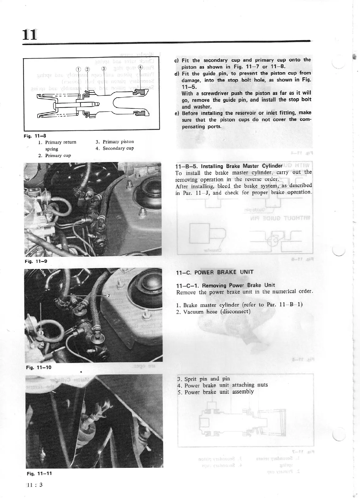
Fig.
11-8
1.
Primary
re
turn
spring
2.
Pr
imary cup
Fig.
11-9
Fig. 11- 11
11
: 3
3. Primary
piston
4.
Secondary cup
•
cl Fit
the
secondary
cup
and primary
cup
onto
the
piston as shown in Fig.
11
- 7
or
11-8.
d)
Fit
the
guide pin,
to
prevent
the
piston cup from
damage, into
the
stop bolt
hole,
as
shown in Fig.
11-5.
With a
sc
rewdriver push the piston as far as
it
will
go, remove
the
guide pin,
and
install
the
stop bolt
and washer.
e) Before
in
stalling
the reservoir
or
inlet fitting, make
sure
that
the
piston cups
do
not
cover
the
com-
pensating ports.
11-
B-5.
Installing
Brake Master Cylinder
To install the brake master cylinder, carry
out
th
e
removing operation in the reverse order.
After installing, bleed the brake system, as described
in Par.
11
- J, and check for proper brake operation.
11-C.
POWER
BRAKE
UNIT
1
1-C-
1. Removing Power Brake
Unit
Remove the power brake unit
in
the numerical order.
1.
Brake master cylinder {refer to Par.
11
- B-
I)
2.
Vacuum hose (disconnect)
3.
Sprit
pin and pin
4. Power brake
unit
attaching nuts
5.
Power brake unit assembly