Fig.10-35
·
Fig.
10
-
36
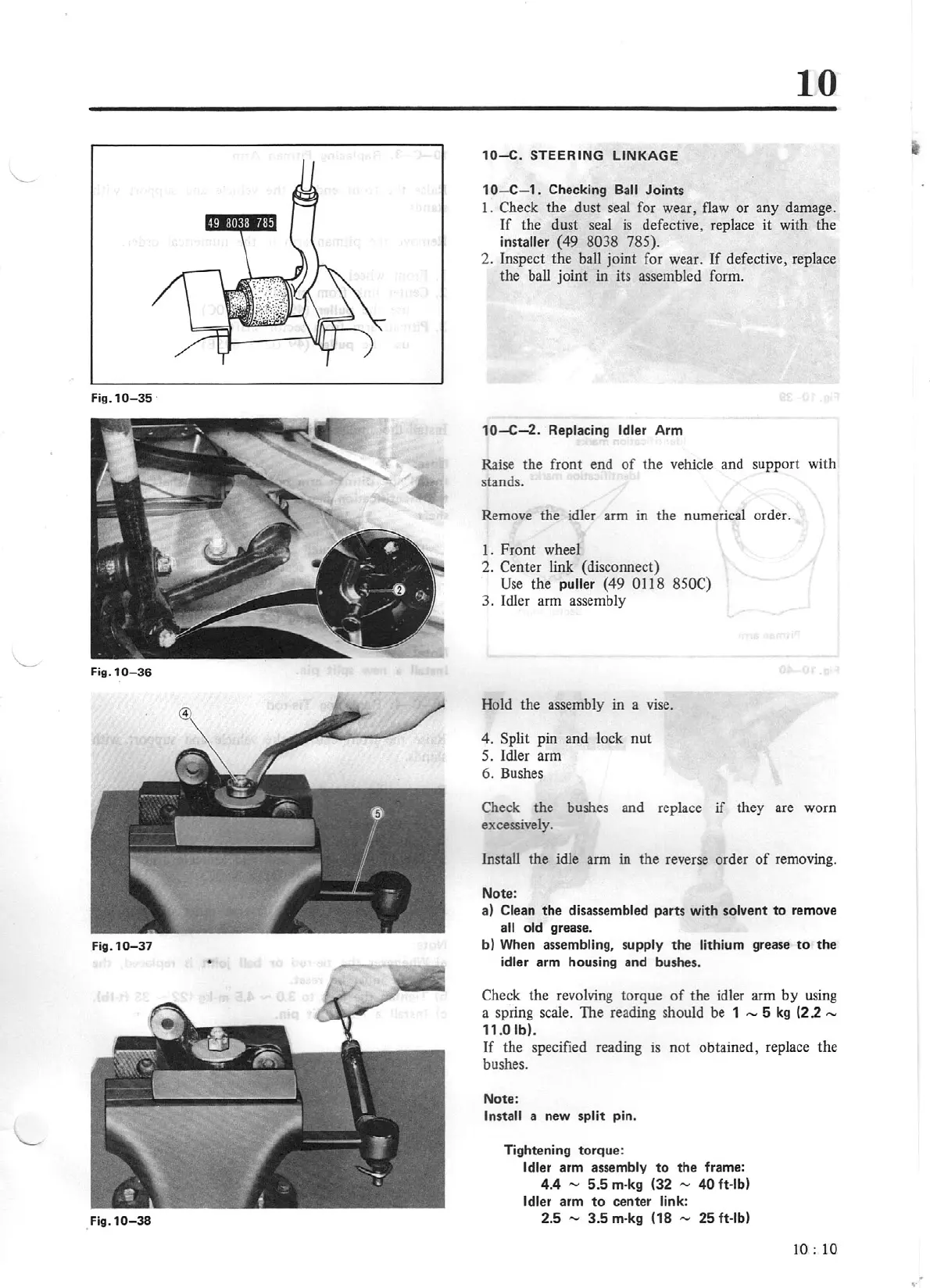
Fig.
10
-
37
.
Fig.10-38
10
10
-C
. STEERING
LINKAGE
1
O-C
-
1.
Checking Ba
ll
Joints
I.
Check the dust seal for wear, flaw or
an
y damage.
If
the dust seal
is
defective, replace
it
with the
installer (
49
8038 785).
2. Inspect the
ba!J
joint for wear.
If
defective, re
pl
ace
the ball joint
in its assembled form.
10
-C-2
. Replacing Idler A
rm
Raise the front end
of
the
vehicle and supp
ort
with
stands.
Remove the idler
arm
in the numerical order.
1.
Front
wheel
2. Center link (disconnect)
Use
the puller (
49
0118 850C)
3. Idler arm assembly
Hold the assembly
in
a vise.
4. Split pin and lock
nut
5.
Idler arm
6.
Bushes
Check the bushes and replace
if
they are worn
excessively.
Install
th
e idle arm in the reverse order
of
removing.
Note:
a) Clean the disassembled parts with solvent
to
remove
all old grease.
b) When assembling, supply
th
e lithium grease
to
the
idler arm housi
ng
and bushes.
Check the revolving torque
of
the idler arm
by
using
a spring scale. The reading should be
1 - 5
kg
(2 2 -
11
.0 lb).
If
the specified reading
is
not obtained, replace the
bushes.
Note:
Install a new split pin.
Tightening torque:
Idler arm assembly
to
the frame:
4.4 - 5.5 m-
kg
(32
,.,_,
40
ft
-lb)
Idler arm
to
center link:
2.5 -
3.5
m-kg
(18
,.,_,
25 ft-lb)
10 : 10
..