F
ig
.
1A
-
58
Fig.1A
-
59
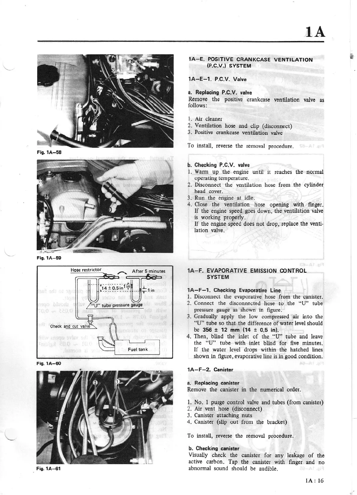
Hose restrictor
Fig.1A-60
Fig.1A-61
lA
1A-E.
POSI
T
IVE
CRANKCASE VENTI LATION
(P.C.V.) SYSTEM
1A-E-1.
P.C.V. Valve
a. Replacing P.C.V. valve
Remove
the
positive crankcase ventilation valve as
follows :
1.
Air cleaner
2. Ventilation hose and clip (disconnect)
3. Positive crankcase ventilation valve
To install, reverse the removal procedure.
b. Checking
P.C
.
V.
valve
I.
Wann up the engine until
it
reaches the normal
operating temperature.
2. Disconnect the ventilation hose from the cylinder
head cover.
3.
Run the engine at idle.
4. Close the ventilation hose opening with finger.
If
the engine speed goes down, the ventilation valve
is
working properly.
If
the engine speed does
not
drop, replace the venti-
lation valve.
1A-F.
EVAPORATIVE EMISSION CONTROL
SYSTEM
lA-F
- 1. Checking Evaporative Line
1.
Disconnect the evaporative hose from the canister.
2.
Connect the disconnected hose
to
the
"U"
tube
pressure gauge
as
shown in figure.
3. Gradually apply the low compress
ed
air into the
"U"
tube so that the difference
of
water level should
be
356
±
12
mm (14 ±
0.5
in).
4.
Then, blind the inlet
of
the
"U"
tube and leave
the
"U"
tube with inlet blind for
five
minutes.
If the water level drops within the hatched lines
shown in figure, evaporative line
is
in good condition.
lA
-
F-2.
Canister
a. Replacing canister
Remove the canister in the numerical order.
1. No. 1 purge control valve and tubes (from canister)
2. Air vent hose (disconnect)
3. Canister attaching nuts
4.
Canister (slip
out
from the bracket)
To install, reverse the removal procedure.
b. Checking canister
Visually check the canister for any leakage
of
the
active carbon. Tap the canister with finger and no
abnormal sound should
be
audible.
lA:
16