Fig.
18
-
20
Fig.
18
-
21
'
Igniti
on
swit:t:h
.
Jumper
-
wire
'
ON
.!.
- - Blue·black wire
.J_
To Engine speed switch
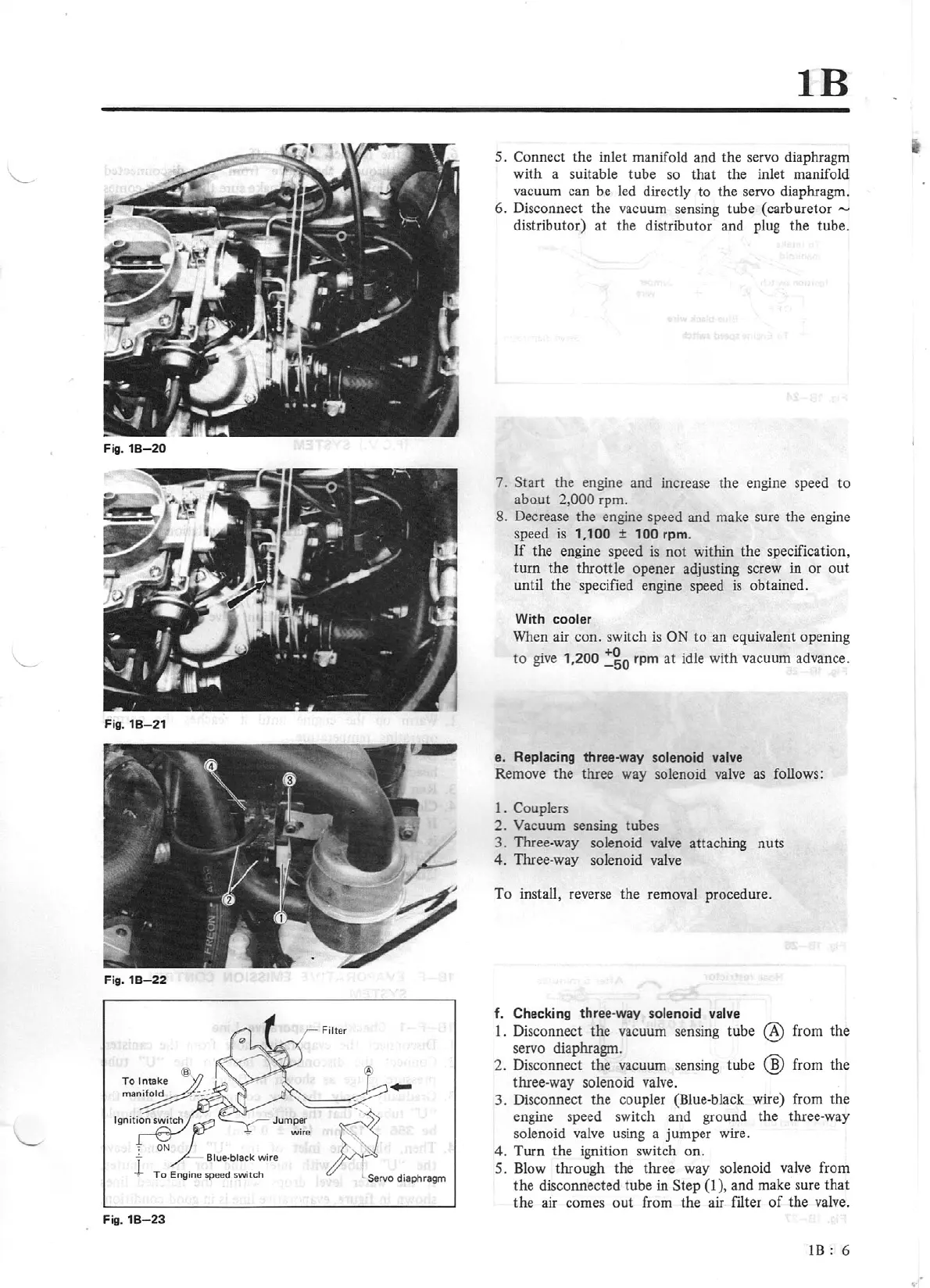
Fig.
18
-
23
IB
5. Connect the inlet manifold and the servo diaphr
agm
with a suitable tube so that the inlet manifold
vacuum can be led directly to the servo diaphragm.
6. Disconnect the vacuum sensing tube (carburetor
""'
distributor) at the distributor and plug the tube.
7. Start the engine and increase the engine speed
to
aboot 2,000 rpm.
8. Decrease the engine speed and make sure the engine
speed
is
1,100 ± 100 rpm.
If
the engine speed
is
not within the specification,
turn the throttle opener adjusting screw in
or
out
until the specified engine speed
is
obtained.
With cooler
When air con. switch
is
ON
to an equivalent opening
to
give
1
,2
00
~go
rpm at idle with vacuum advance.
e.
Replacing three-way solenoid
valve
Remove the three way solenoid valve as fo
ll
ows:
1. Couplers
2.
Vacuum sensing tubes
3. Three-way solenoid valve attaching nuts
4. Three-way solenoid valve
To install, reverse the removal procedure.
f. Checking three
-way
so
leno
id
valve
1.
Disconnect the vacuum sensing tube @ from the
servo diaphragm.
2. Disconnect the vacuum sensing tu
be
@ from the
three-way solenoid valve.
3. Disconnect the coupler (Blue-black wire) from the
engine speed switch and ground the three-way
solenoid
valve
using a jumper wire.
4.
Turn the ignition switch on .
5.
Blow
through the three way
so
lenoid
valve
from
the disconnected tube in Step
(1
), and make sure that
the air comes
out
from the air filter
of
the
valv
e.
1B:
6