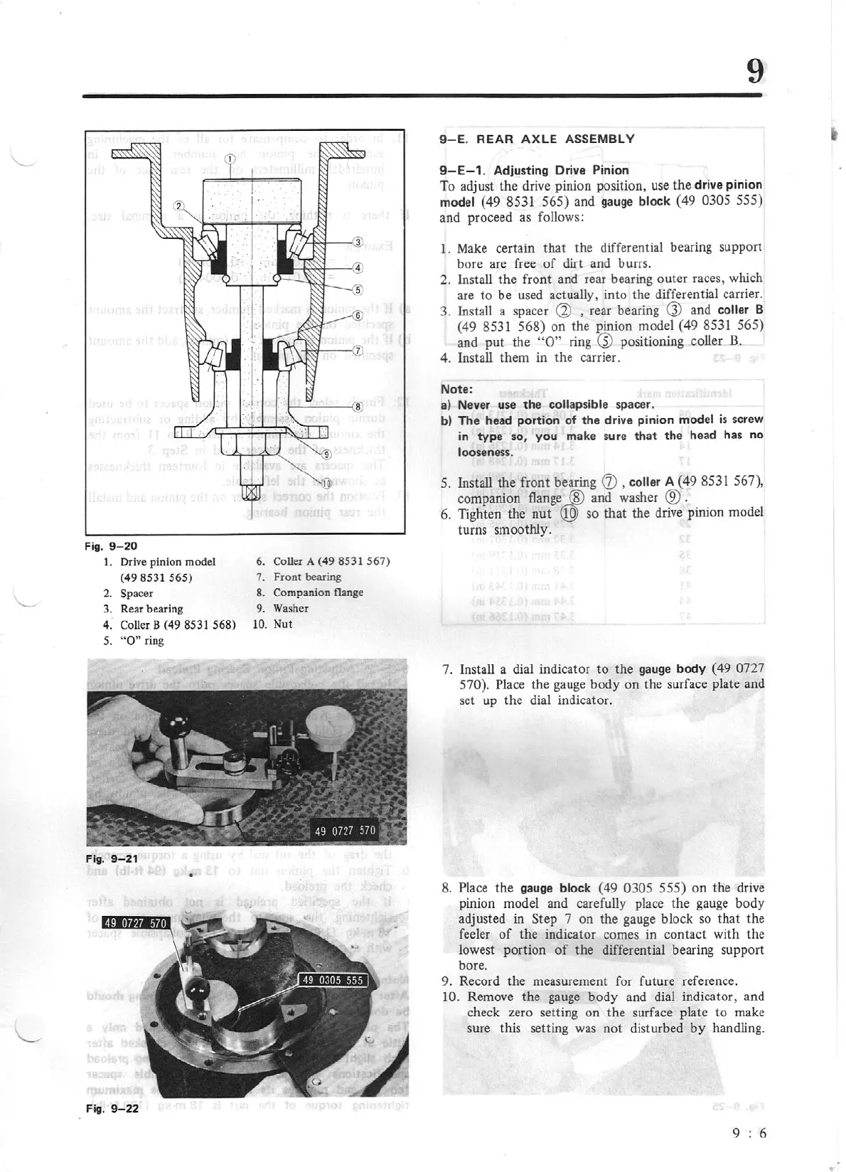
Fig. 9-
20
I.
Drive pinion model 6. Coller A
(49
8531 567)
(49 8531 565)
7.
Front bearing
2.
Spacer
8. Companion flange
3.
Rear beari
ng
9.
Washer
4. Coller B (49 8531 568)
1
0.
Nut
5.
"O"
ring
Fig.
9-21
•
Fig.
9-
22
9
9-E
. REAR AXLE
ASSEMBLY
9-E-1
.
Adjusting Drive Pinion
To adjust the drive
pinion
position, use
the
d
rive
pinion
model
{49
8531 565)
and gauge block {49
0305
555)
and proceed as follows:
1. Make certain
that
the differential bearing support
bore arc free
of
dirt and burrs.
2. Install
the
front and rear bearing outer races, which
are
to
be used actually, into the differential carrier.
3. Install a spacer
~
, rear bearing
G)
and
collar
B
(49
8531
568)
on the pinion model (49
8531 565)
and
put
the
"O"
ring
~
positioning coller
B.
4. Install them in the carrier.
Note:
a)
Never use
the
collap
si
ble
spacer.
b) The head portion of the drive pinion
model
is
screw
in
type
so, you make sure
that
the head has no
looseness.
5.
Install the front bearing
Q)
,
coller
A (49
8531
567),
companion
flange...@
and washer
®
.
6. Tighten the
nut
Q9)
so
that
the drive pinion model
turns smoothly.
7. Install a dial indicator to the gauge body ( 49
0727
570).
Place
the gauge body
on
the surface plate and
set up the dial indicator.
8.
Place
the gauge
block
(49
0305 555)
on
the drive
pinion model and carefully place the gauge body
adjusted in Step 7 on the gauge block so that the
feeler
of
the indicator comes
in
contact with the
lowest portion
of
the differential bearing support
bore.
9. Record the measurement for future reference.
10.
Remove the gauge body and dial indicator, and
check zero setting on the surface plate
to
make
sure this setting was not disturbed
by
handling.
9 6
...