Fig.
4-13
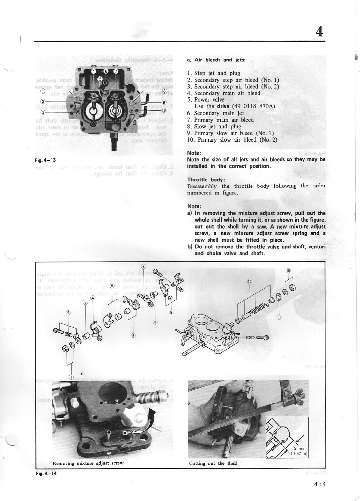
Removing mixture adjust screw
Fig. 4-
14
a. Air bleeds and jets:
1.
Step jet and plug
2. Secondary step air bleed (No. 1)
3. Secondary step air bleed (No. 2)
4. Secondary main air bleed
5. Power
valve
Use
the drive (49 0118 870A)
6.
Secondary main jet
7.
Primary main air bleed
8. Slow jet and plug
9.
Primary slow air bleed (No. 1)
10. Primary slow air bleed (No. 2)
Note:
4
Note
the
size
of
all
jets and air bleeds so they may
be
installed in
the
correct position.
Throttle body:
Disassembly the throttle body following the order
numbered
in
figure.
Note:
a)
In removing
the
mixture adjust screw, pull
out
the
whole shell while turning it,
or
as shown in the figure,
cut
out
the
shell by a saw. A new mixture adjust
screw, a new mixture adjust screw spring and a
new shell must
be fitted in place.
b)
Do
not
remove
the
throttle
valve
and shaft, venturi
and choke valve and shaft.
Cutting out the shell
4:4