13
Fig.
13-38
Fig.
13-39
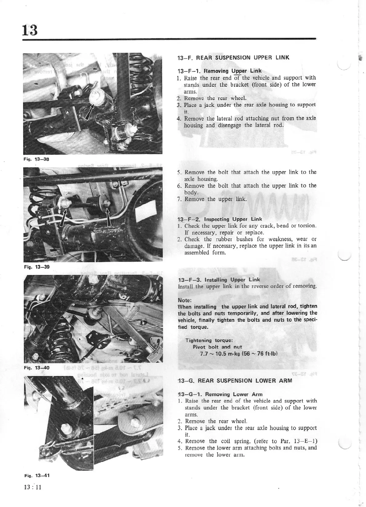
Fig.
13-41
13
:
11
13
-
F.
REAR
SUSPENSION UPPER LINK
13
-
F-1.
Removing
Upper
Link
1.
Raise
the
rear end
of
the
vehicle and support with
stands under the bracket
(front
side)
of
the
lower
arms.
2.
Remove the rear wheel.
3.
Place
a jack under
the
rear axle housing to support
it.
4. Remove
the
lateral rod attaching
nut
from
the
axle
housing and disengage the lateral rod.
5.
Remove
the
bolt that attach
the
upper link
to
the
axle housing.
6. Remove
the
bolt
that
attach
the
upper link
to
the
body.
7. Remove
the
upper link.
13
- F-
2.
Inspecting
Upper
Link
I
. Check the upper link for any crack, bend
or
torsion.
If
necessary, repair
or
replace.
2. Check the rubber bushes for weakness, wear
or
damage.
lf
necessary, replace
the
upper link
in
its an
assembled form.
13-F-3.
Installing
Uppe
r Link
Install
the
upper link in the reverse order
of
removing.
Not
e:
When installing
the
upper
link
and
lateral
rod,
tighten
the
bolts
and
nuts
temporarily
,
and
after
lowering
th
e
v
ehic
l
e,
finally
tighten
the
bolts
and
nuts
to
the
speci-
fied
torque.
Tightening
torque
:
Pivot
bolt
and
nut
7.7
-
10.5
rn-kg
(5
6
-
76
ft
-lb)
!
13
-
G.
REAR
SUSPENSION LOWER
ARM
!13-G- 1.
Removing Lower
Arm
1. Raise
the
rear end
of
the vehicle and support with
stands under
the
bracket (front side)
of
the
lower
arms.
2. Remove
the
rear wheel.
3.
Place a jack under
the
rear axle housing to support
it.
4.
Remove the coil spring. (refer to Par. 13- E-
l)
5.
Remove
the
lower arm attaching bolts and nuts, and
remove the lower arm.
..