14
The
bumper
will
move
with
the
groove as a
gu
i
de
if a
l
oad
is
applied.
Fig.
14-9
1
450-
SIOnvn
(
17
.72- 20.08
m)
Fig.
14-10
Fig.
14-11
Fig.
14-12
14:
3
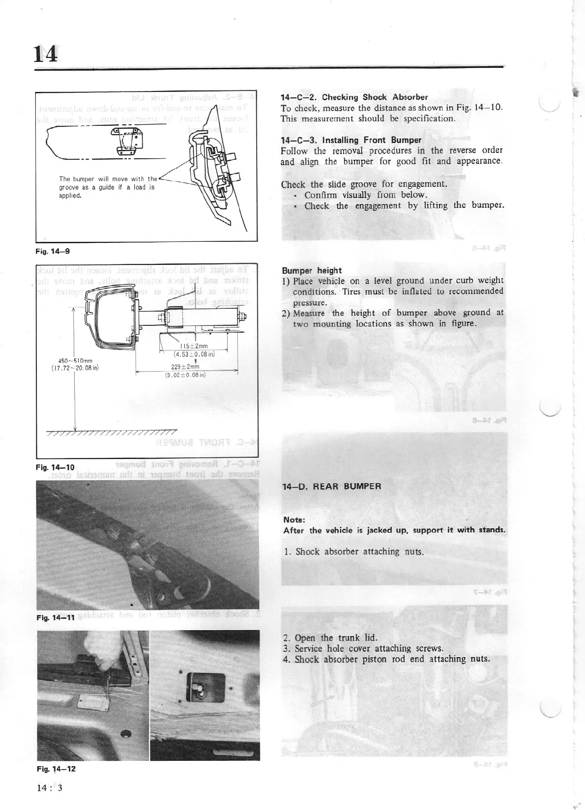
14-C-2
. Checking
Shock
Absorber
To check, measure the distance as shown
in
Fig.
14-10.
This measurement should be specification.
14-C-3.
Installing
Front
Bumper
Follow the removal procedures in the reverse order
and align .the bumper for good fit and appearance.
Check
the
slide groove for engagement.
•
Confirm visually from below.
• Check the engagement by lifting the bump
er
.
Bumper height
1) Place
vehicle on a level gr
ou
nd under curb weight
conditions. Tires must be inflated
lo
recommended
pressure.
2)
Measure the height
of
bumper above ground
at
two
mounting locations as shown in figure.
14
-0.
REAR
BUMPER
Note:
Aft
er
the
vehicle is jacked
up,
support
it with stands.
1. Shock absorber attaching nuts.
2. Open the
trunk
lid.
3.
Service hole cover attaching screws.
4.
Shock absorber piston rod end attaching nuts.