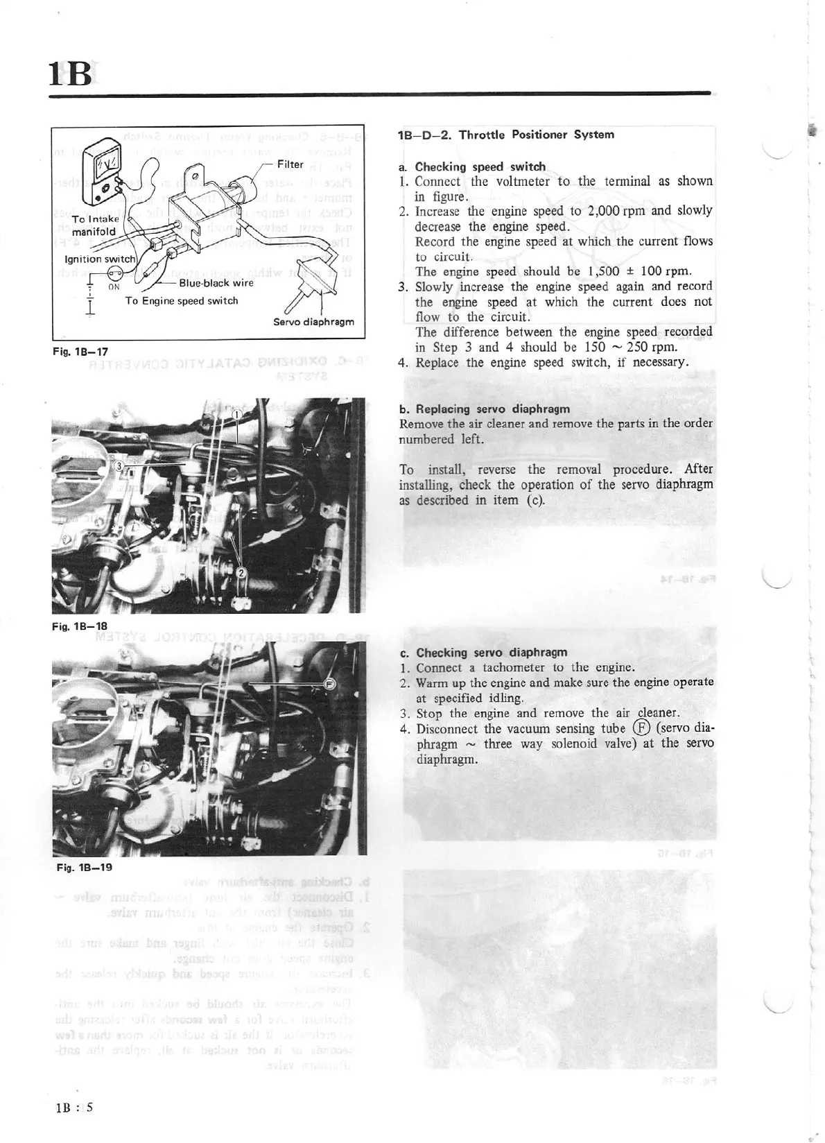
lB
Filter
l
To
Engine speed switch
Ser
vo
diaphragm
Fig.
18-
17
Fig.
1
8-
18
Fig.
18-
19
lB
:
5
1
B-D-2.
T
hrott
le Positioner System
a. Checking speed switch
t.
Connect the
vo
lbneter
to
the tenninal as shown
in figure.
2. Increase the engine speed to 2,000
rpm and slowly
decrease the engine speed.
Record the engine speed at which the current flows
to
circuit.
The engine speed should be
I ,500
±
I
00
rpm.
3. Slowly increase the engine speed again and record
the engine speed at which the current does not
flow
to
the circuit.
The difference between the e
ng
ine speed recorded
in Step 3 and 4 should be
150 - 250
r
pm
.
4. Replace
th
e engine speed switch,
if
necessary.
b.
Replacing servo diaphragm
Remove the air cleaner and remove the parts in
th
e order
numbered left.
To
install, reverse the removal procedure. After
installing, check the operati
on
of
the servo diaphragm
as descnoed in item (c).
c. Checking servo diaphragm
1. Connect a tachometer to the engine.
2.
Warm up the engine and make sure the engine operate
at specified idling.
3. Stop the en
gi
ne and remove
the
air cleaner.
4.
Disconnect
th
e vacuum sensing tube
®
(servo
dia-
phragm
-
three way solenoid valve) at
the
se
rvo
diaphragm.