7B
Fig.
78-65
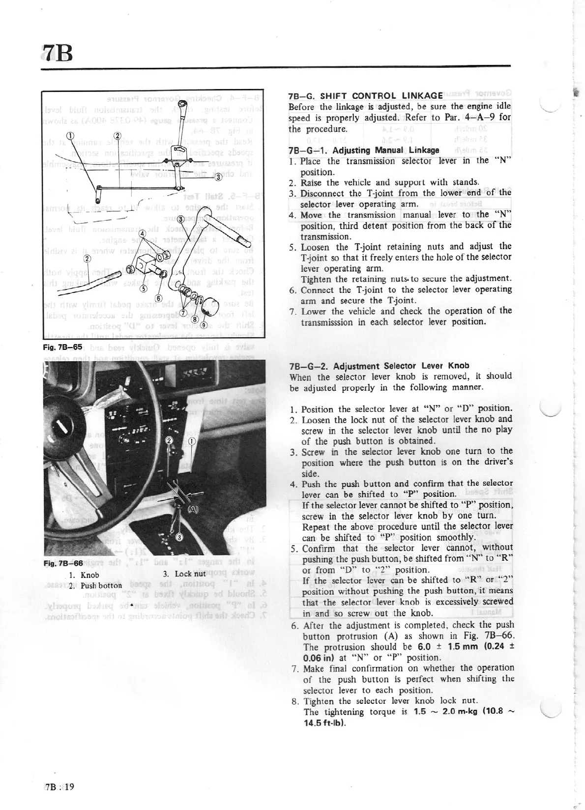
Fi
g.
78
-
66
1.
Knob
3. Lock
nut
2.
Push
botton
•
7B:
19
78-G.
S
HIFT
CONTROL LINKAGE
Before the linkage
is
adjusted,
be
sure the engine idle
speed
is
properly adjusted. Refer to Par.
4-
A
-9
for
the procedure.
78
-
G-1.
Adjusti
ng
Manual
Linkage
1. Place the transmission selector lever in the
"N"
position.
2. Raise the vehicle and support with stands.
3. Disconnect the T-joint from the lower end
of
th
e
selector lever operating arm.
4.
Move
the transmission manual lever to the
"N"
position, third detent position from the back
of
the
transmission.
5. Loosen the
T·joint
retaining nuts and adjust the
T-joint so
that
it freely enters the hole
of
the selector
lever operating arm.
Tighten
the retaining
nuts.
to secure the adjustment.
6.
Connect the T-joint
to
the selector lever operating
arm and secure the T-joint.
7. Lower the vehicle and check the operation
of
the
transmisssion in each selector lever position.
78-G-2.
Adjustment
Selector
Lever Knob
When
the selector lever knob
is
removed, it should
be adjusted properly in the following manner.
1. Position the selector lever at
"N"
or
"O"
position.
2. Loosen the lock
nut
of
the
selector lever knob and
screw in the selector lever knob until the
no
play
of
the push
button
is
obtained.
3. Screw in the selector lever knob one turn
to
the
position where the push
button
is
on
the driver's
side.
4. Push the push
button
and confirm that the selector
lever can be shifted
to
"P"
position.
If
the selector lever cannot be shifted
to
"P" position,
screw in the selector lever knob
by
one turn.
Repeat the above procedure until the selector lever
can
be
shifted
to
"P"
position smoothly.
5. Confirm
that
the selector lever cannot, without
pushing the push
button,
be shifted from
"N"
to
"R"
or from
"D"
to
"2"
position.
If
the selector lever can be shifted to
"R"
or
"2"
position without pushing the push
button,
it means
that the selector lever knob
is
excessively screwed
in and so screw
out
the knob.
6. After the adjustment
is
completed, check the push
button
protrusion (A) as shown
in
Fig.
78-66.
The protrusion should be
6.0
±
1.5
mm
(0.24
±
0.06
in)
at
"N"
or
"P"
position.
7.
Make
final confirmation
on
whether the operation
of
the push
button
is
perfect when shifting the
selector lever
to
each position.
8. Tighten the selector lever knob lock nut.
The tightening torque
is
1
.5
- 2.0
m-kg
(10.8
-
14.5 ft-lb).