lB
Filter
...
wire
'
OFF
•,,.
f
Blue-black
wire
·.
Ignition
swit~
-.
Jumper
~
-.
f-
To
Engine speed switch Servo diaphragm
Fig.
18-24
Fig.
18
-
25
Fig.
18-26
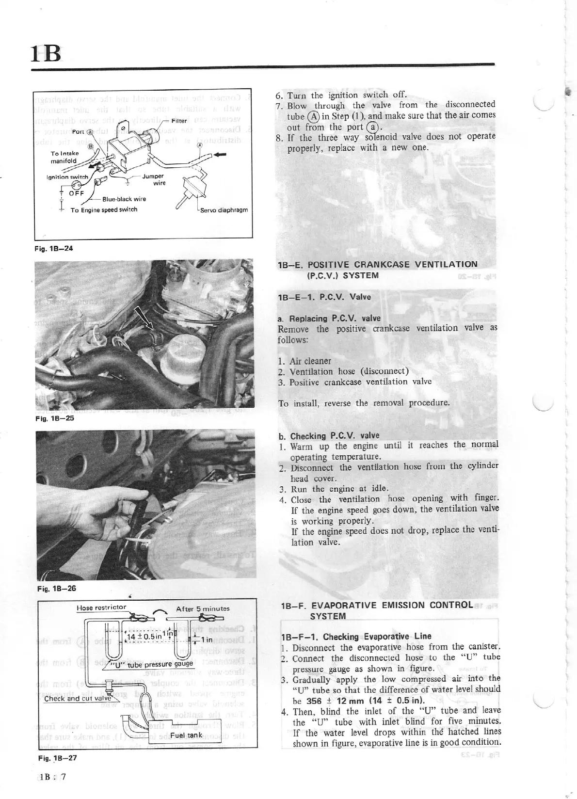
Hose restrictor
Fig.
18
-
27
lB:
7
.L
1
·
.
T
in
6. Turn the ignition switch off.
7.
Blow through the valve from the disconnected
tube
@in
Step
(I),
and make sure that the air comes
out
from the
port
(a).
8.
rr
the three way
sOtenoid valve does not operate
properly, replace with a new one .
18-E.
POSITIVE
CRANKCASE
VEN
TILATION
(P.C.V.)
SYSTEM
18-E-1
. P.C.V. Valve
a.
Replacing
P.C.
V. valve
Remove
the
positive crankcase ventilation valve
as
follows:
1.
Air
cleaner
2.
Ventilation hose (disconnect)
3.
Positive crankcase ventilation valve
To install, reverse the removal procedure.
b.
Checking P.C.V.
valve
1.
Warm up the engine until it reaches the normal
operating temperature.
2.
Disconnect the ventilation hose from the cylinder
head cover.
3.
Run the engine at idle.
4.
Close the ventilation hose opening with finger.
If
the engine speed goes down, the ventilation valve
is
working properly.
If
the engine speed does not drop, replace the
venti-
lation valve.
18
-F.
EVAPORATIVE
EMISSION CONTROL
SYSTEM
18-F-1
. Checking Evaporative Line
1.
Disconnect the evaporative hose from the canister.
2.
Connect the disconnected hose
to
the
"U"
tube
pressure gauge as shown in figure.
3.
Gradually apply the low compressed air into the
"U"
tube so
that
the difference
of
water level should
be
356
±
12
mm
(14 ±
0.5
in).
4. Then, blind
th
e inlet
of
the
"U"
tube
and leave
the
"U"
tube with inlet blind for
five
minutes.
If
the water level drops within
the
hatched lines
shown in figure, evaporative line
is
in good condition.