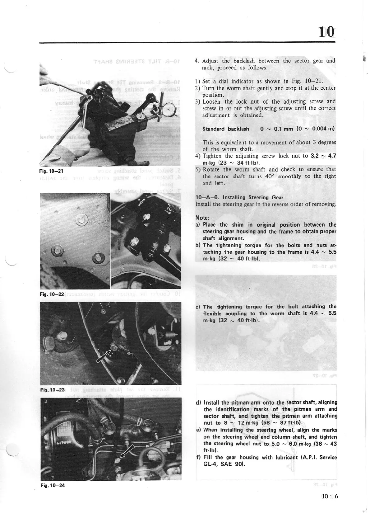
Flg.10-21
Flg
.
10-22
Fig
.
10
-23
Fig.
10-24
10
4. Adjust the backlash between the sector gear and
rack, proceed as follows.
1)
Set
a dial indicator as shown in Fig. 10
-2
1.
2
) Turn the worm shaft gently and stop
it
at the center
position.
3)
Loosen the lock
nut
of
the adjusting screw and
screw
in
or
out the adjusting screw until the correct
adjustment
is
obtained.
Standard backlash
0 - 0.1
mm
(0 - 0.
004
in)
This
is
eq
uivalent to a movement
of
about 3 degrees
of
the worm shaft.
4) Tighten the adjusting
sc
rew lock
nut
to
3.2
-
4.7
m·
kg
(23 -
34
ft
·lb).
5)
Rotate the worm shaft and check to ensure that
the sector shaft turns
40°
smoothly
to
the right
and left.
10-A-6.
Installing Steering
Gear
Install the steering gear in the reverse order
of
removing.
Note:
a)
Place
the
shim
in
original
poS1t1on
between the
steering gear housing and
the
frame
to
obtain proper
shaft alignment.
b) The tightening
torque
for
the
bolts and nuts
at·
taching
the
gear housing
to
the
frame
is
4.4
-
5.5
m-kg (32
-
40
ft·lb).
c) The tightening torque for
the
bolt
attaching
the
flexib
le
coupling
to
the
worm shaft
is
4.4 -
5.5
m-kg (32
-
40
ft-lb).
d)
Install
the
pitman arm
onto
the
sector shaft, aligning
the
identification marks
of
the
pitman arm and
sector shaft, and tighten
the
pitman arm attaching
nut
to
8
-
12
m-kg (58 -
87
ft
·lb).
e) When
installing
the
steeri
ng
wheel,
align
the
marks
on
the
steering wheel and column shaft, and tighten
the steering
wheel
nut
to
5.0
- 6.0 m·kg
(36
-
43
ft-lb).
fl
Fill
the
gear housing with
lubricant (A.P.I. Service
GL-4, SAE 90).
1
0:
6