15
15-L.
METER SET
15-L-1.
Checking
Meter Set Print
Panel
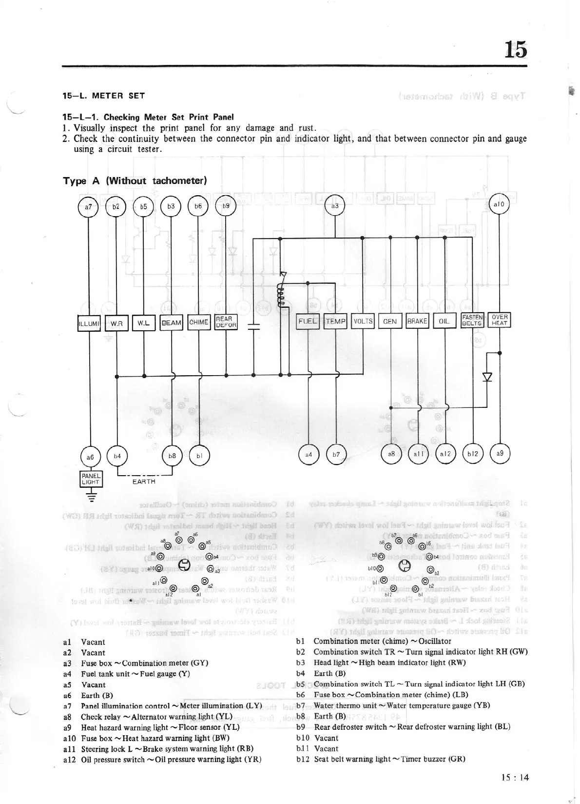
l . Visually inspect
the
print panel for any damage and rust.
2. Check
the
continuity between the connector pin and indicator light, and
that
between connector pin and gauge
using a circuit tester.
Type A (Without tachometer)
al
Vacant
a2 Vacant
a3 Fuse box
-Combination
meter
(GY}
a4 Fuel tank unit - Fuel gauge
(Y)
a5 Vacant
a6 Earth (B)
a7 Panel illumination control - Meter illumination (LY)
a8 Check relay - Alternator warning light (YL)
a9 Heat hazard warning light - Floor sensor (YL)
a 10 Fuse
box
- Heat hazard warning light
(BW)
al
1 Steering lock L - Brake system warning light (RB)
a12
Oil
pressure switch
-Oil
pressure warning light (YR)
a
lO
bl
Combination meter (chime)
-oscillator
b2 Combination switch
TR
-Turn
signal indicator light RH
(GW)
b3 Head light - High beam indicator light (RW)
b4 Earth (B)
bS
Combination switch
TL-Turn
signal indicator light
LH
(GB)
b6 Fuse box
-combination
meter (chime) (LB)
b7 Water thermo unit
-Water
temperature gauge
(YB}
b8 Earth (B)
b9 Rear defroster switch - Rear defroster warning light (BL)
blO Vacant
b.11
Vacant
bl2
Seat belt warning light
-Timer
buzzer (GR)
15
: 14
•
,.
 Loading...


