13
Fig
.
13
-2
4
•
I
•
•
'
- -
-
...(..
•
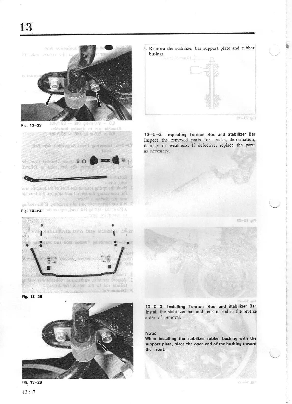
Fig.
13-25
Fig.
13-26
13:
7
•
'
•
•
•
~
ij
S.
Remove the stabilizer bar support plate and rubber
busings.
.-/
13
- C- 2. Inspecting
Tension Rod and
Sta
bilizer
Bar
Inspect the removed parts for cracks, defonnation,
damage
or
weakness.
If
defective, replace the parts
as
necessary.
13-C-3.
Installing
Tension Rod and Stabilizer Bar
Install the stabilizer bar and tension rod
in
the reverse
order
of
removal.
Note:
When
installing
the
stabilizer rubber bushing with
the
support
plate, place
th
e open end
of
the
bu
sh
ing toward
the front.