7B
Fig.
78
-
70
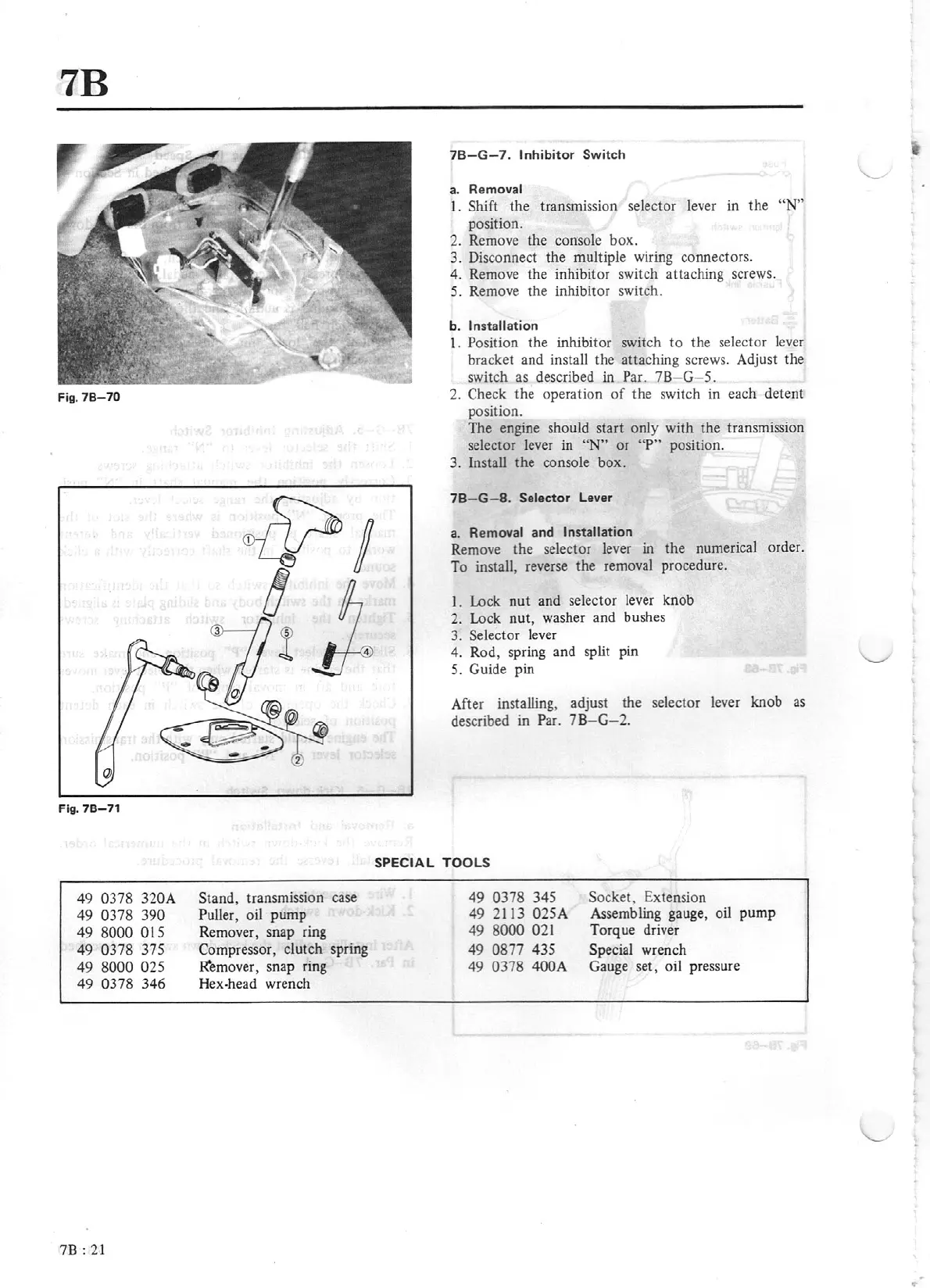
Fig.
78-71
49
0378
320
A
49
0378
390
49
8000
015
49
0378
375
49
80
00
025
49
0378
3
46
78 :
21
Stand,
transm1ss1on
case
Pu
ller,
oil
pump
Remover, snap ring
Compressor, clutch spring
R"emover
,
s
nap
ring
Hex-head wre
nch
78-
G-7.
Inhibitor
Switch
a.
Removal
l .
Shift
the transmission selector lever in
the
"N"
position.
2.
Remove the console
box.
3.
Disconnect
the
multiple wiring connectors.
4.
Remove the inhibitor switch attaching screws.
5.
Remove the inhibitor switch.
b.
Insta
ll
ation
1.
Position the inhibitor switch
to
the
selector lever
bracket and install
the
attaching screws. Adjust the
switch
as
described
in
Par. 7
B G 5.
2.
Check
the
operation
of
the switch in each
detent
position.
The engine should start only
with
the transmission
selector lever in
"N"
or
"P"
position.
3.
Install
the
console box.
78-G
- 8.
Select
or
Lever
a.
Removal
and Installation
Remove the selector lever in the numerical order.
To install, reverse the removal procedure.
I.
Lock
nut
and
sel
ector
lever knob
2.
Lock
nut,
washer
and
bushes
3.
Selector
lever
4.
R
od,
spring
and
split pin
5.
Guide pin
After installing, adjust the sele
ctor
lever knob
as
described in
Par.
78-G-2.
SPECIAL TOOLS
49
0378
345
49
2113
025A
49
8000
021
49
0877
435
49
0378
400A
Socket,
Extension
Assembling gauge, oil
pump
Tor
que
driver
Special
wrench
Gauge set, oil
pr
essure
I
..