4A
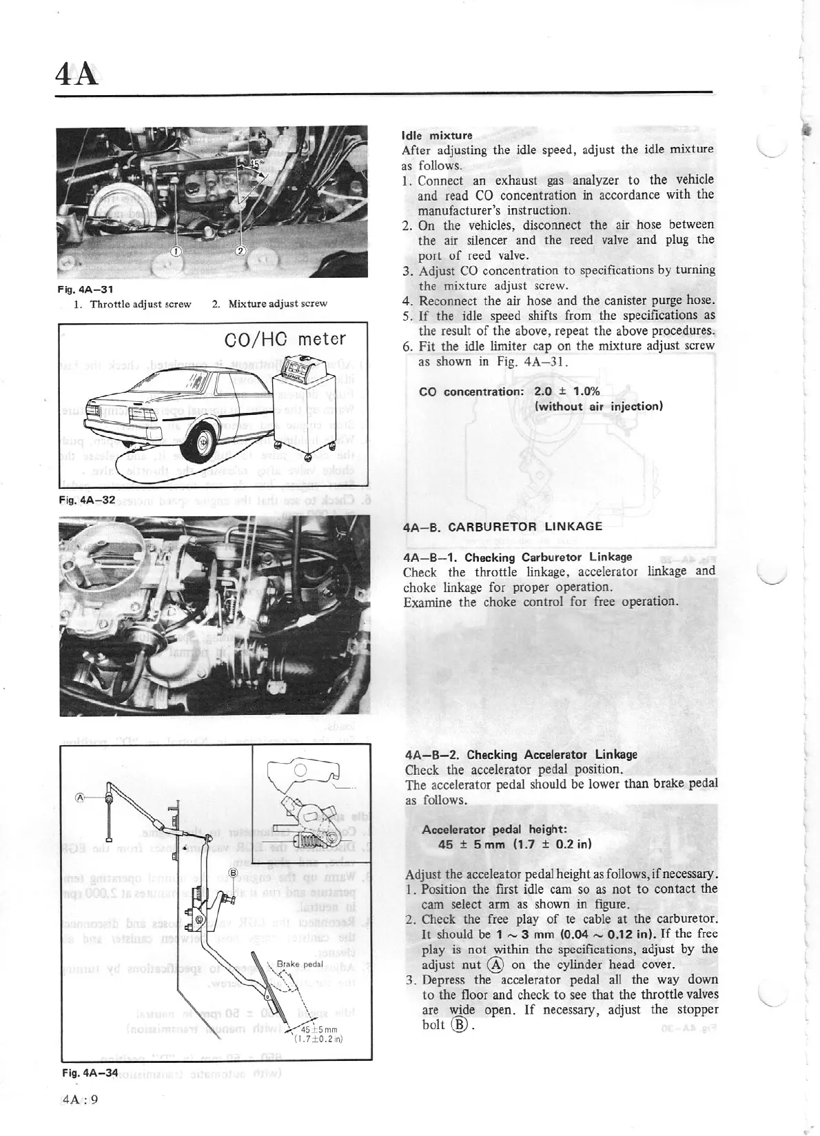
Fig.
4A-31
1.
Throttle adjust screw
2.
Mixture adjust screw
CO
/
HC
meter
Fig.
4A-32
Fig.
4A-34
4A
:9
Idle
mixture
After adjusting
the
idle speed, adjust
the
idle mixture
as follows.
1. Connect an exhaust gas analyzer
to
the
vehicle
and
read CO
concentration in accordance with the
manufacturer's instruction.
2.
On
the vehicles, disconnect
the
air hose between
the air silencer and
the
reed
valve
and plug
the
port
of
reed valve.
3.
Adjust
CO
concentration
to
specifications by turning
the mixture adjust screw.
4.
Reconnect
the
air hose
and
the canister purge hose.
5.
If
the idle speed shifts from the specifications as
the result
of
the
above, repeat
the
above procedures.
6. Fit
the
idle limiter cap
on
the
mixture adjust screw
as shown
in
Fig.
4A
-3
1.
CO
co
ncentration:
2.0
±
1.0%
(without air injection)
4A-
B.
CARBURETOR LINKAGE
4A-B-1.
Checking Carburetor Linkage
Check the
throttle
linkage, accelerator linkage and
choke linkage for proper operation.
Examine
the
choke control
for
free operation.
4A-B-2.
Checking
Accelerator
Linkage
Check the accelerator pedal position.
The accelerator pedal should be lower than brake pedal
as follows.
Accelerator pedal
height:
45
± 5
mm
(1.7 ±
0.2
in
)
Adjust the acceleator pedal height as follows,
if
necessary.
I.
Position
the first idle cam so
as
not
to
co
nta
ct
the
cam select
arm
as shown in figure.
2.
Check the free play
of
te cable
at
the carbu
re
tor.
It
should
be 1
.....,
3
mm (0.04....., 0.
12
in).
If
the free
play is
not
within the specifications, adjust by
the
adjust
nut
@
on
the
cylinder head cover.
3.
Depress the accelerator pedal all the way down
to
the floor
and
check
to
see
that
the throttle valves
are wide
open.
If necessary, adjust the stopper
bolt@.