Fig.
7A-21
Fig.
7A
-
22
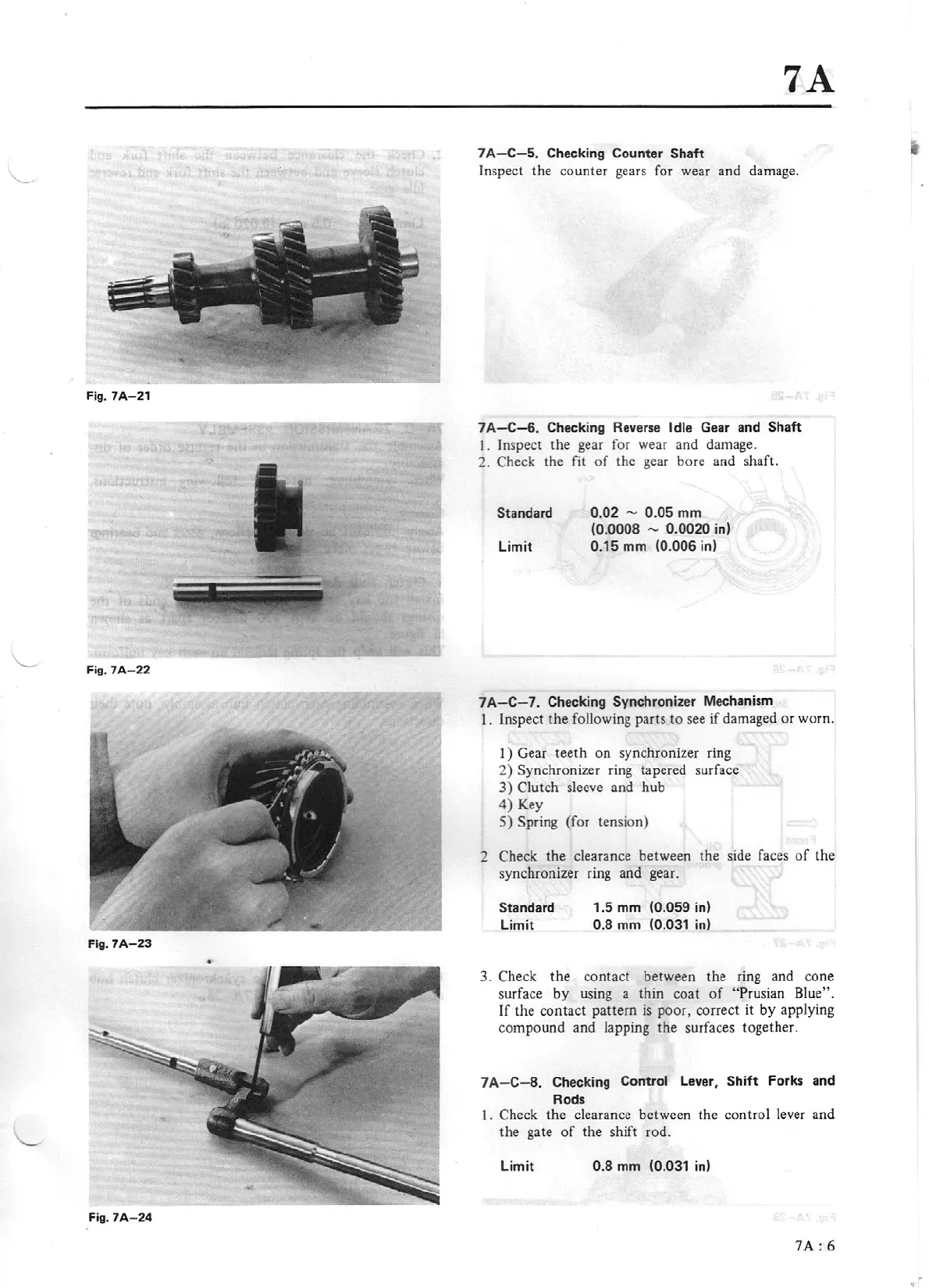
Fig.
7A-23
Fig.
7A
-
24
7A
7A
-C
- 5. Checking Counter Shaft
Inspect the counter gears for wear and damage.
7A
-C-6
. Checking
Re
ver
se
Idle
Gear
and Shaft
I.
Inspect the gear for wear
and
damage.
2. Check the fit
of
the gear bore and shaft.
St
an
da
rd
Limit
0.
02
- 0.
05
mm
(0.0008 - 0.0020
in
)
0.
15
mm (0.006 in)
7A-
C-7.
Checking Synchroniz
er
Mechanism
I.
Inspect the following parts
to
see
if
damaged
or
worn.
I)
Gear
teeth
on
synchronizer ring
2) Synchronizer ring tapered surface
3)
Clutch sleeve and
hub
4) Key
5)
Spring (for tension)
2 Check
the
clearance between the side faces
of
the
synchronizer ring
and
gear.
Standard
Limi
t
1.5 mm (0.059 in)
0.8 mm (0.031 in)
3. Check the contact between the ring and cone
surface
by
using a
thin
coat
of
"Prusian Blu
e"
.
If
the contact pattern is p
oo
r, correct it by applying
compound and lapping
the
surfaces together.
7
A-
C- 8. Checking Control Lever,
Shift
Forks and
Rods
1. Check the clearance between the control lever and
the gate
of
the
shift rod.
Li
m
it
0.8 mm (0.031 in)
7
A:
6