10
Fig.
10-4
5
Po
si
tion
90°
(B1)
180°
(
B2)
- 90° (B
J)
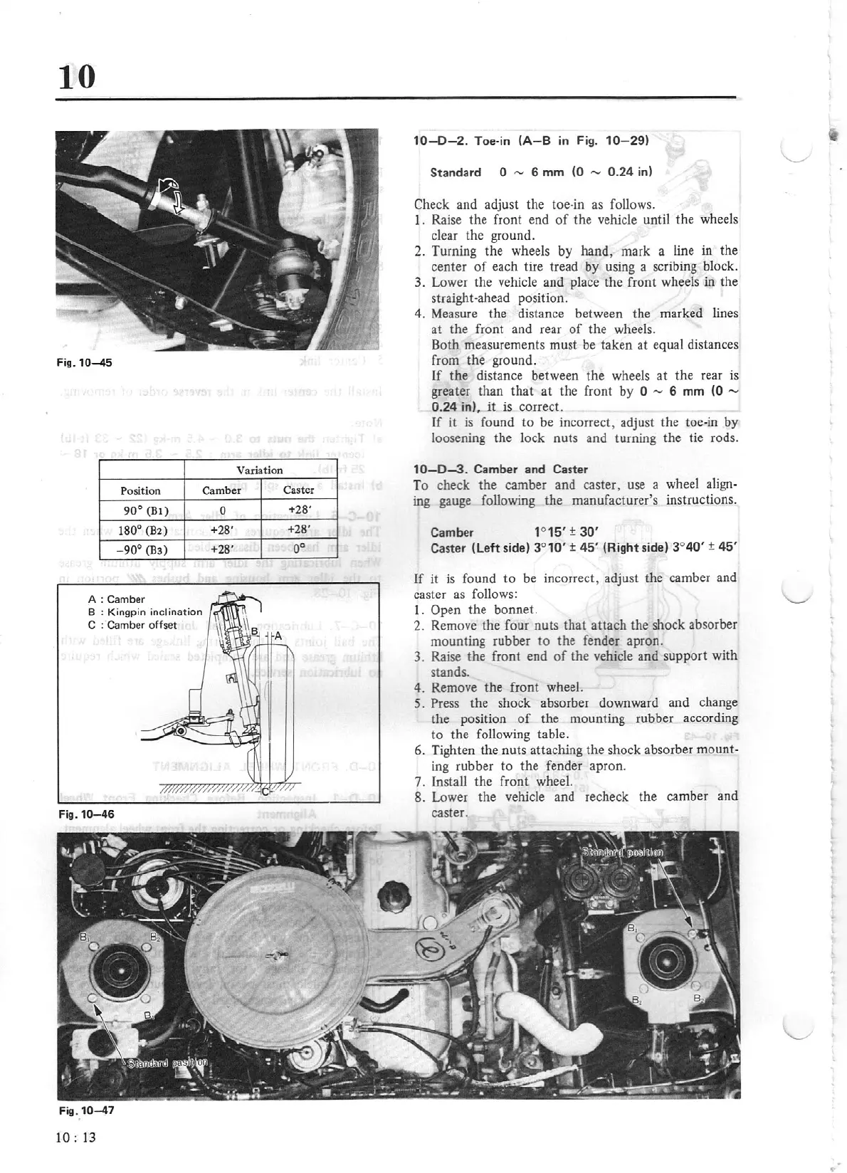
A:
Camber
B : K
ingpin
inclination
C : Camber offset
Fig.10-46
Fig.
10-47
1
0:
13
Variation
Camber
0
+
28
'
+2
8'
Caster
+28'
+28'
oo
10-0
-2.
Toe·in
(A
- 8 in
Fi
g.
10-
29)
Standard 0
"'
6 mm
(0
-
0.24
i
n)
Check
and adjust the toe-in as follows.
l.
Raise the front end
of
the vehicle until the wheels
clear the ground.
2. Turning the wheels
by
hand, mark a line in the
center
of
each tire tread by using a scribing block.
3. Lower the vehicle and place the front wheels in the
straight-ahead position.
4. Measure the distance between the marked lines
at
the front and rear
of
the wheels.
Both measurements must be taken at equal distances
from the ground.
If the distance between the wheels
at
the rear
is
greater than
that
at the front
by
O -
6 mm
(0 -
0.24
in),
it
is correct.
If
it
is
found
to
be incorrect, adjust the toe-in
by
loosening the lock nuts and turning the tie rods.
1
0-
0
-3
.
Camber and C
as
ter
To check the camber and caster, use a wheel
align-
ing gauge following the manufacturer's instructions.
Camber 1°
15
'
±
30
'
Caster
(L
e
ft
side)
3°
10
'
±
4
5'
(Right side)
3°
40'
±
45
'
If
it
is
found
to
be incorrect, adjust the camber and
caster
as
follows:
I .
Open the bonnet.
2. Remove the four
nuts
that attach the shock absorber
mounting rubber
to
the fender apron.
3. Raise the front end
of
the vehicle and support with
stands.
4. Remove the
front
wheel.
5.
Press the shock absorber downward and change
the position
of
the mounting rubber accor
di
ng
to
the following table.
6. Tighten the
nuts
attaching the shock absorber
mount
-
ing rubber
to
the fender apron.
7. Install the front wheel.
8. Lower the vehicle and recheck the camber and
caster.
..