11
Fig.
11-24
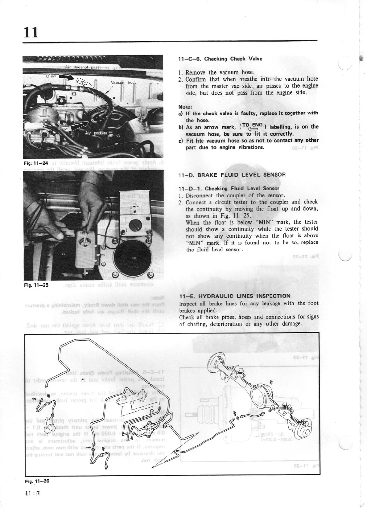
Fig.
11-25
Flg.11
-
26
11:
7
11
-
C-6.
Checking Check
Valve
I . Remove the vacuum hose.
2. Confirm
that when breathe
int
o the vacuum hose
from the master vac side, air passes
to
the engine
side,
but
does
not
pass from the engine side.
Note:
a)
If
the
check valve
is
faulty, replace
it
together with
the hose.
b)
As
an arrow mark, (
TO
~G
)
labelling,
is on the
vacuum hose,
be
sure
to
fit
it
correctly.
c) F
it
hte vacuum hose so as
not
to
contact any other
part
due
to
engine vibrations.
11- D. BRAKE
FLUID
LEVEL
SENSOR
11
- D- 1. Checking
Fluid
Level
Sensor
1. Disconnect the coupler
of
the sensor.
2.
Connect
a circuit tester
to
the coupler and check
the continuity
by
moving the float up and down,
as shown
in
Fig.
11-25.
When the float is below
"MIN"
mark, the tester
should show a continuity while the tester should
not
show any continuity when the float
is
above
"MI
N"
mark.
If
it
is
found not to be so, replace
the fluid level sensor.
11
- E.
HYDRAULIC LINES INSPECTION
Inspect all brake lines for any leakage with the foot
brakes applied.
Check
all
brake pipes, hoses and connections for signs
of
chafing, deterioration or any other damage.
..