Fig.
78
-2
9
Fig.
78-30
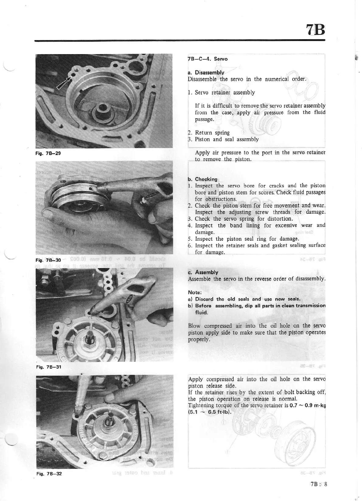
Fig.
78-3
1
Fig.
78-32
7B
78-C-4.
Servo
a. Disassembly
Disassemble
the
servo in
the
numerical order.
I.
Servo
re
tainer assembly
If
it
is
difficult
to
remove the servo retainer assembly
from
the
case, apply air pressure from the fluid
passage.
2.
Return
spring
3. Piston and seal assembly
Apply air pressure
to
the
port
in
the
servo retainer
to
remo
ve
the
piston.
b.
Checking
I . Inspect
the
servo bore for cracks and the piston
bore
and piston stem for scores.
Check
fluid passages
for obstructions.
2.
Check
the
piston stem for free movement
and
wear.
Inspect
the
adjusting screw threa
ds
for damage.
3.
Check
the
servo spring for distortion.
4. Inspect
the
band
lining for excessive wear and
damage.
5. Inspect
the
piston seal ring for damage.
6.
inspect
the
retainer seals and gasket sealing surface
for damage.
c.
Assembly
Assemble
the
servo in
the
reverse order
of
disassembly.
Note:
a)
Discard
the
old seals and use new seals.
b) Before assembling, dip
all
parts in clean transmission
fluid.
Bl
ow compressed
au
mto
the
oil hole
on
the
servo
piston apply side
to
make sure
that
the piston operates
properly.
Apply compressed air into the oil hole
on
the
servo
piston release side.
If
the retainer rises
by
the
extent
of
bolt
backing off,
the
piston operation
on
release is normal.
Tightening
torque
of
the
servo retainer is
0.7 - 0.9 m-kg
(5.1
-
6.5
ft-lb).
78 : 8