Fig. 11-
58
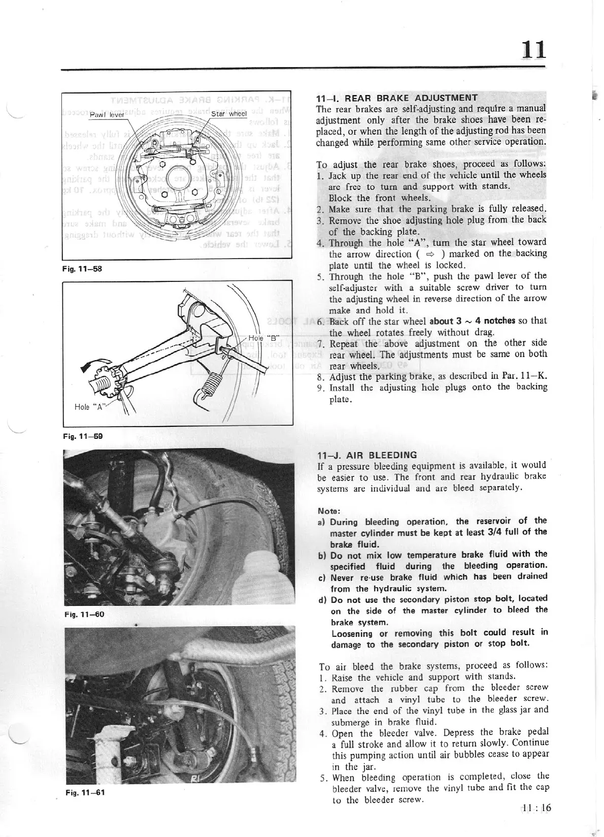
Fig.
11-59
Fig.
11
-60
Fig.
11
-61
ll
11
-
1.
REAR BRAKE
ADJUSTMENT
The rear brakes are self-adjusting and
requlre
a manual
adjustment only after the brake shoes have been
re-
placed, or when the length
of
the adjusting rod has been
changed while performing same other
se
rvice operation.
To adjust the rear brake shoes, proceed
as
follows:
1.
Jack
up
the rear end
of
the vehicle until the wheels
arc
free
to
turn and supp
ort
with stands.
Block the front wheels.
2. Make sure
that
the parking brake
is
fully released.
3. Remove the shoe adjusting hole plug from the back
of
the backing plate.
4.
Through the hole
"A
",
tum
the star wheel toward
the arrow direction (
<=:>
)
marked on the backing
plate until the wheel
is
locked.
5. Through the hole "B
",
push the pawl lever
of
the
self-adjuster with a suitable screw driv
er
to t
um
the adjusting wheel
in
reverse direction
of
the arrow
make and hold it.
6.
Back
off
the star wheel
about
3
-
4 notches so
that
the wheel rotates freely without drag.
7. Repeat the above adjustment on the other side
rear wheel. The adjustments must be same
on
both
rear wheels.
8. Adjust the parking brake, as described in Par.
11
- K.
9.
Install the adjusting hole plu
gs
onto
the backing
plate.
11-J
.
AIR
BLEEDING
If
a pressure bleeding equipment
is
ava
iJa
ble, it would
be easier to use. The front and rear hydraulic brake
systems are individual and are bleed separately.
Note:
a) Duri
ng
bleeding operation. the reservoir of the
master
cylinder
must
be
kept
at
least
3/4
full
of the
brake fluid.
b) Do not mix
low temperature brake
fluid
with the
specified
fluid
during the bleedi
ng
operation.
c) Never re·use
brake fluid
which has been drained
from the
hydraulic system.
d)
Do
not use the secondary piston stop
bolt, located
on the side of the master
cylinder
to
bleed
the
brake system.
Loosening
or
removing this
bolt could result
in
damage
to
the secondary piston or stop
bolt.
To air
bleed the brake systems, proceed
as
follows:
1. Raise the vehicle and support with stands.
2. Remove the rubber cap from the bleeder screw
and attach a vinyl tube lo the bleeder
sc
rew.
3.
Place
the end
of
the vinyl tube
in
the glass jar and
submerge in brake fluid.
4. Open
the bleeder valve. Depress the brake pedal
a full stroke and
allow
it
to
return slowly.
Continue
this pumping action until air bubbl
es
ce
ase
to appear
in the jar.
5.
When
bleeding operation
is
completed, close the
bleeder valve, remove the vinyl tube and
fit
the cap
to
the bleeder screw.
11
:
16