5
Fig. 6-
69
Fig.
5-60
Fig.
5-61
Fig.
6-62
5:
17
5-G-3.
Inspecting
Distributor
Inspect
the
following parts and replace
if
necessary.
a.
Checking
cap
Inspect
the
distributor cap for cracks, carbon runners
and evidence
of
arcing. If
any
of
these conditions
exists,
the
cap should be replaced. Clean any corroded
hightension terminals.
b. Checking
rotor
Inspect
the
rotor for cracks or evidence
of
excessive
burning at
the
end
of
the metal strip.
If
any
of
these
conditions exists,
the
rotor
should be replaced.
c. Pick-up
coil
Check the resistance
of
the pick-up coil.
Standa
rd
800
ohms
±
10
%
at
20
°C (68°F)
5-G
-4.
Assembling Distributor
Assemble the distributor
in
the reverse order
of
disas·
sembly, noting
the
following points.
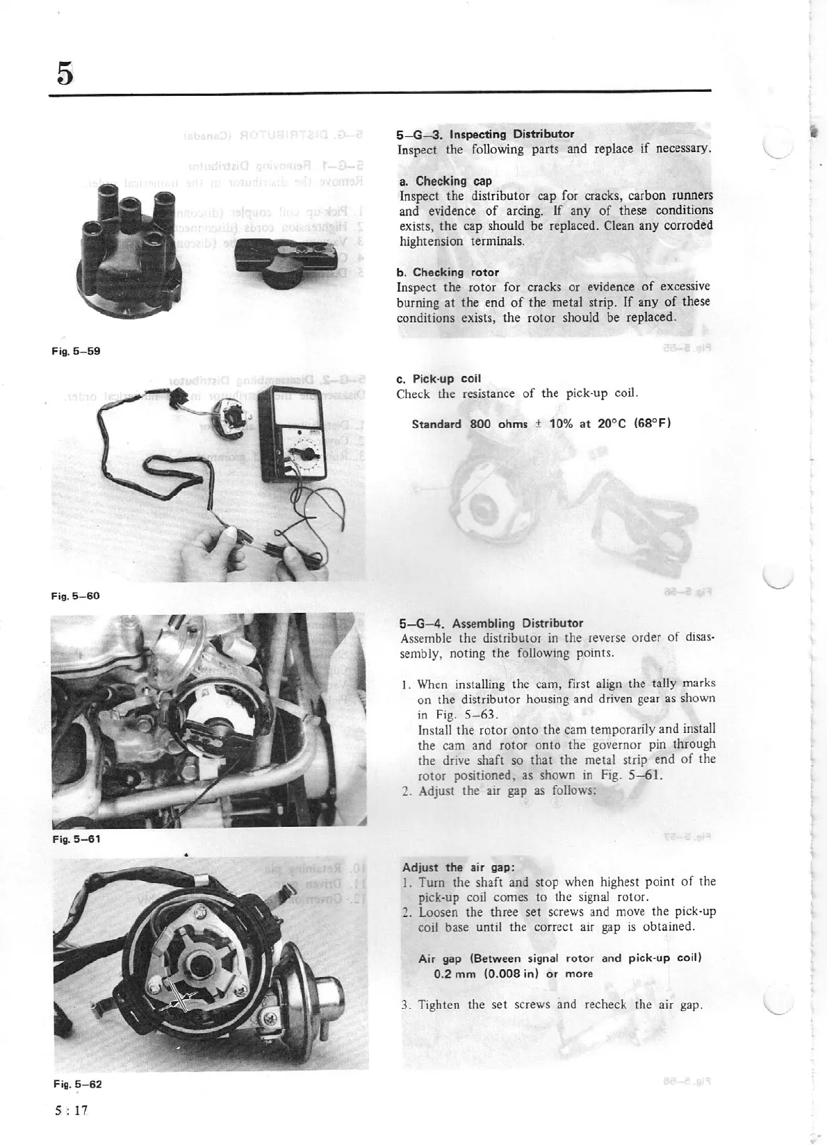
I.
When insta
ll
ing
th
e cam, first align the tally marks
on
the distributor housing and driven gear as shown
in
Fig.
5-63.
In
stalJ the rotor
onto
the
cam temporarily and install
the cam and rotor
onto
the
governor pin through
the drive shaft so
that
the metal strip
end
of
the
rotor
positioned, as shown
in
Fig.
5-61.
2. Adjust
the
air gap as follows:
Adjust
the
air gap :
I.
Turn the shaft and stop when highest point
of
the
pick-up coil comes
to
the signal rotor.
2. Loosen the three set screws and move the
pi
ck·up
coil base
until the correct air gap
is
obtained.
Air gap (Between
signal
rotor
and pick-up
co
il)
0.2
mm
(0.008
in)
or
more
3. Tighten the set screws and recheck the air gap.