4
Fig. 4- 9
Fig.
4-10
Fig.
4-
11
Fig.
4-12
4:3
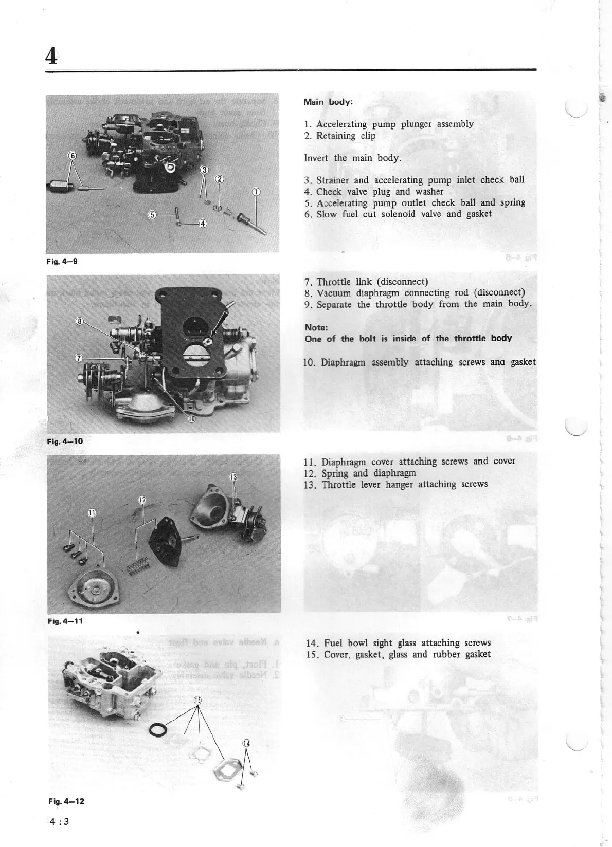
Main
body:
I. Accelerating pump plunger assembly
2.
Retaining clip
Invert the main body.
3. Strai
ne
r and accelerating pump inlet check ball
4.
Check v
al
ve plug and washer
5.
Accelerating pump
ou
tlet check ball and spring
6.
Slow
fuel cut solenoid
valve
and gasket
0
7. Throttle
link
(disconnec
t)
8. Vacuum diaphragm connecting rod (disconnect)
9.
Separate the tluottle body from the main body.
Note:
One
of
the
bolt
is
inside of the
th
rottte
body
10.
Diaphragm assembly attaching screws
ana
gasket
11. Diaphragm cover attaching screws and cover
12. Spring
and diaphragm
13. Throttle lever hanger
atta
ching screws
14. Fuel bowl sight glass attaching screws
15. Cover, gasket,
glass
and rubber gasket