Fig.
9-26
•
•
Fig.
9-27
Fig.
9-28
Fig.
9-29
9
7.
While
observing the preceding note, carefully set
the preload drag at 9 -
14
cm-kg
(7
.8
-
12.2
in·lb)
plus the oil seal drag determined in Step 5.
Note:
If
the
preload
is
measured
by
using a spring scale
at
the
bolt
hole
of
the
companion
flange,
the
preload
drag
is
2.5
- 4.0 kg (5.5
....
8.8
lb).
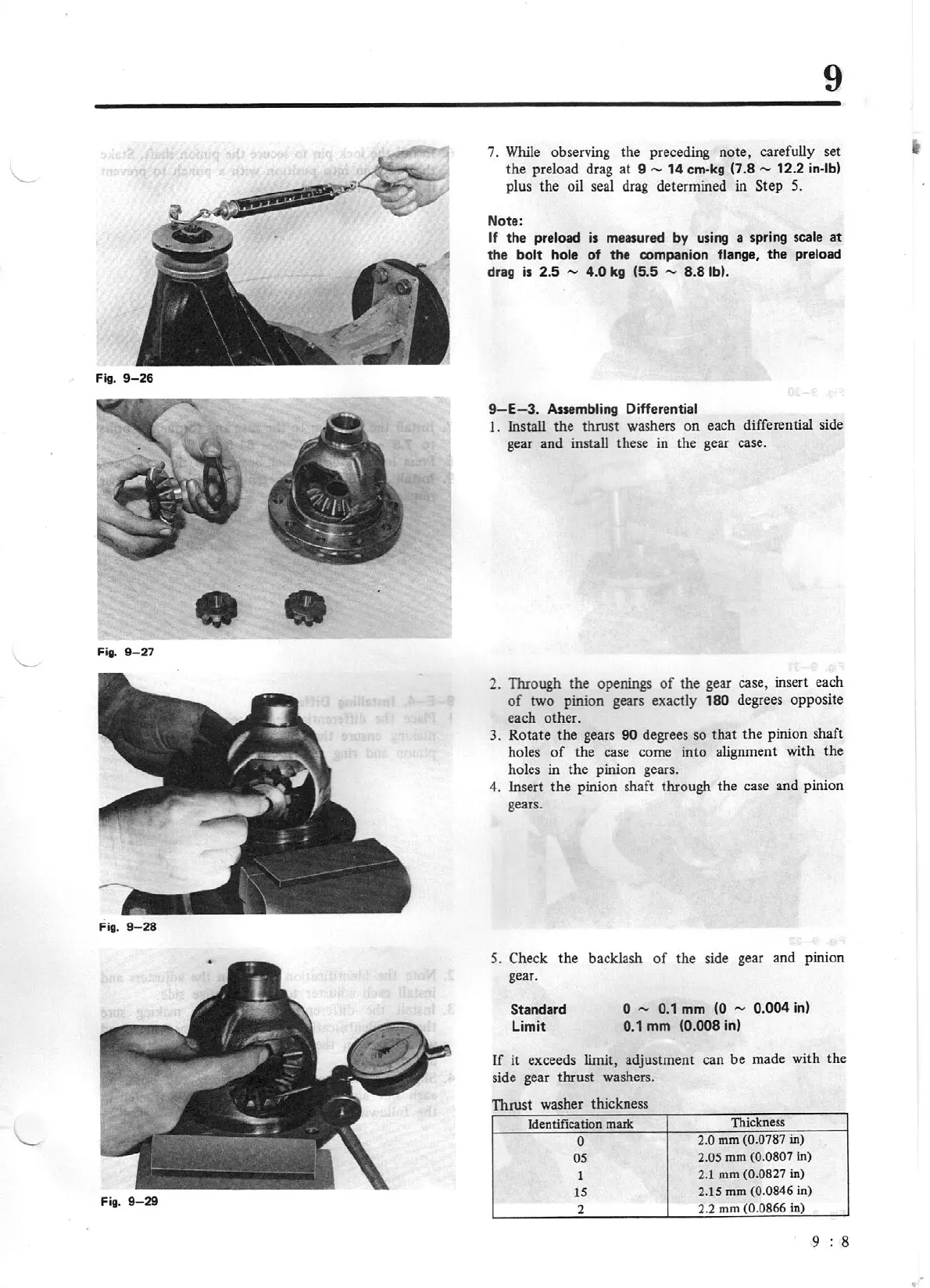
9-E-3
.
Assembling Differential
1.
Install the thrust washers on each differential side
gear and install these in the gear case .
2.
Through the openings
of
the gear case, insert each
of
two pinion gears exactly 180 degrees opposite
each other.
3. Rotate the gears
90
degrees so that the pinion shaft
holes
of
the case come into alignme
nt
with the
holes in the pinion gears.
4. Insert the pinion shaft through the case and pinion
gears.
5. Check the backlash
of
the side gear and pinion
gear.
Standard
Limit
0 - 0.1
mm
(0 - 0.004
in)
0.1
mm
(0.008
in)
If
it exceeds limit, adjustment can be made with the
side gear thrust washers.
Thrust washer thickness
Identification mark
Thickness
0
2.0 mm
(0.0787
in)
05
2.05
mm
(0.0807
in)
1
2.1 mm
(0
.0827
in)
15
2.15 mm
(0.0846
in)
2
2.2 mm (0.0866
in)
9 8