5
Fig.
5-29
Fig,
6-3
0
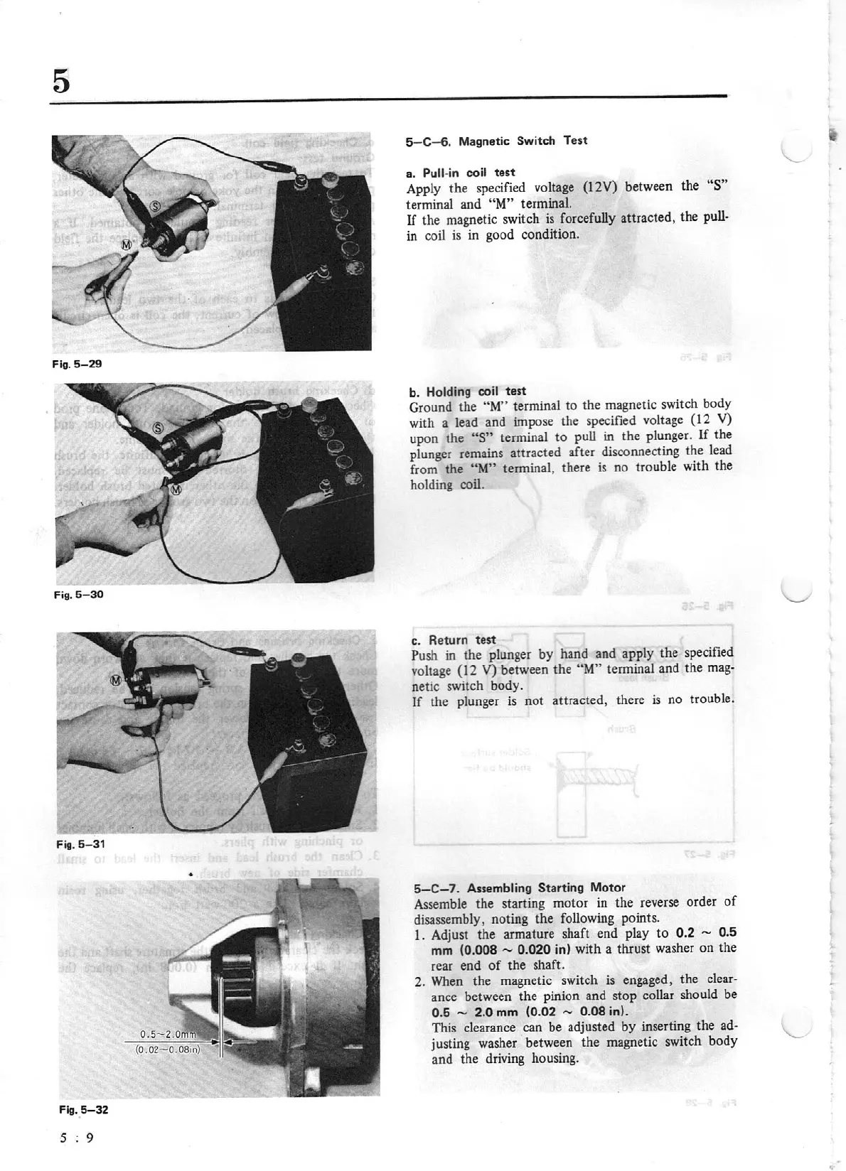
Fig. 5-
32
5 :
9
5-C-6.
Ma
gn
et
ic
Switch
T
est
a.
Pull-in
co
il
test
Apply the specified
vo
ltage
(l
2V)
between t
he
"S"
terminal and
"M"
terminal.
If
the magnetic switch
is
forcefully attracted, the
pu
ll
-
in coil
is
in good condition.
b.
Holding coil
te
st
Gr
ound the
"M"
terminal to the magnetic switch body
with a lead and impo
se
the specified v
olt
age
(12
V)
u
pon
the
"S"
terminal
to
pull in the plunger.
If
the
plunger remains attracted after disconnecting the lead
from the
"M"
terminal, there is no trouble with the
holding coil.
c.
Return
test
Push in the plunger
by
hand and apply the specified
voltage
(12
V)
between the
"M"
terminal and the
mag-
netic switch body.
If the plunger
is
not attracted, there is no trouble.
5-C-7.
As
se
mbl
in
g
Starting Motor
Assemble the starting motor in the reverse order
of
disassembly, noting
the
following points.
1. Adjust the armature shaft end play
to
0.2
~ 0.5
mm
(0.008 - 0.
020
in) with a thrust washer
on
the
rear end
of
the shaft.
2. When the magnetic switch
is
engaged, the clear-
ance between the pinion and stop collar should be
0.5 - 2.0
mm
(0.
02
- 0.
08
in).
This clearance can be adjusted
by
inserting the
ad-
justing washer between the magnetic
sw
it
ch
body
and the driving housing.