IB
Fig.
lB-32
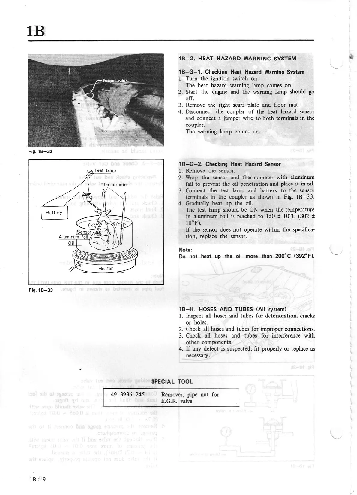
Fig.
lB-33
49 3936 245
1B
; 9
18-G
.
HEAT
HAZARD
WARNING
SYSTEM
18
-G-1.
Checking
Hea
t Hazard Warning System
1. Turn the ig
ni
tion switch
on
.
The heat hazard warning lamp comes on.
2. Start the engine and the warning lamp should
go
off.
3. Remove the right scarf plate and floor ma
t.
4. Disconnect the coupler
of
the heat hazard sensor
and conne
ct
a jumper wire
to
both terminals in the
coupler.
The warning lamp comes on.
18
- G- 2. Checking
Hea
t Hazard Sensor
I.
Remove the sensor.
2.
Wrap
the sensor and thermometer wi
th
aluminum
fail
to
prevent the oil penetration and place it in oil.
3. Connect
the
test lamp and battery
to
the
se
nsor
terminals in
the
coupler
as
shown in Fi
g.
lB
- 33.
4. Gradually heat up the oil.
The test lamp should be ON
wh
en the temperature
in aluminum foil
is
reached
to
150 ± 10°C (302 ±
18°F).
If
the
se
ns
or does not operate within·
th
e specifica-
tion, replace the sensor.
Note:
Do
not
heat up the
oi
l more than 200°C (392° F).
1
8-H
. HOSES A
ND
TUBES
(All
system)
1. Inspect all hoses and tubes for deterioration, cracks
or holes.
2. Check all hoses and tubes for improper connect
io
ns.
3. Check
all hoses and tubes for interference with
other components.
4.
If
any defect
is
suspected,
fit
properly or replace
as
necessary.
SPECIAL
TOOL
Remover, pipe nut for
E.G.
R.
valve