11
Fig. 11-
31
Fig.
11-32
..-.,
--
.
_,,
-
Fig, 11-
33
Fig.
11-34
11
: 9
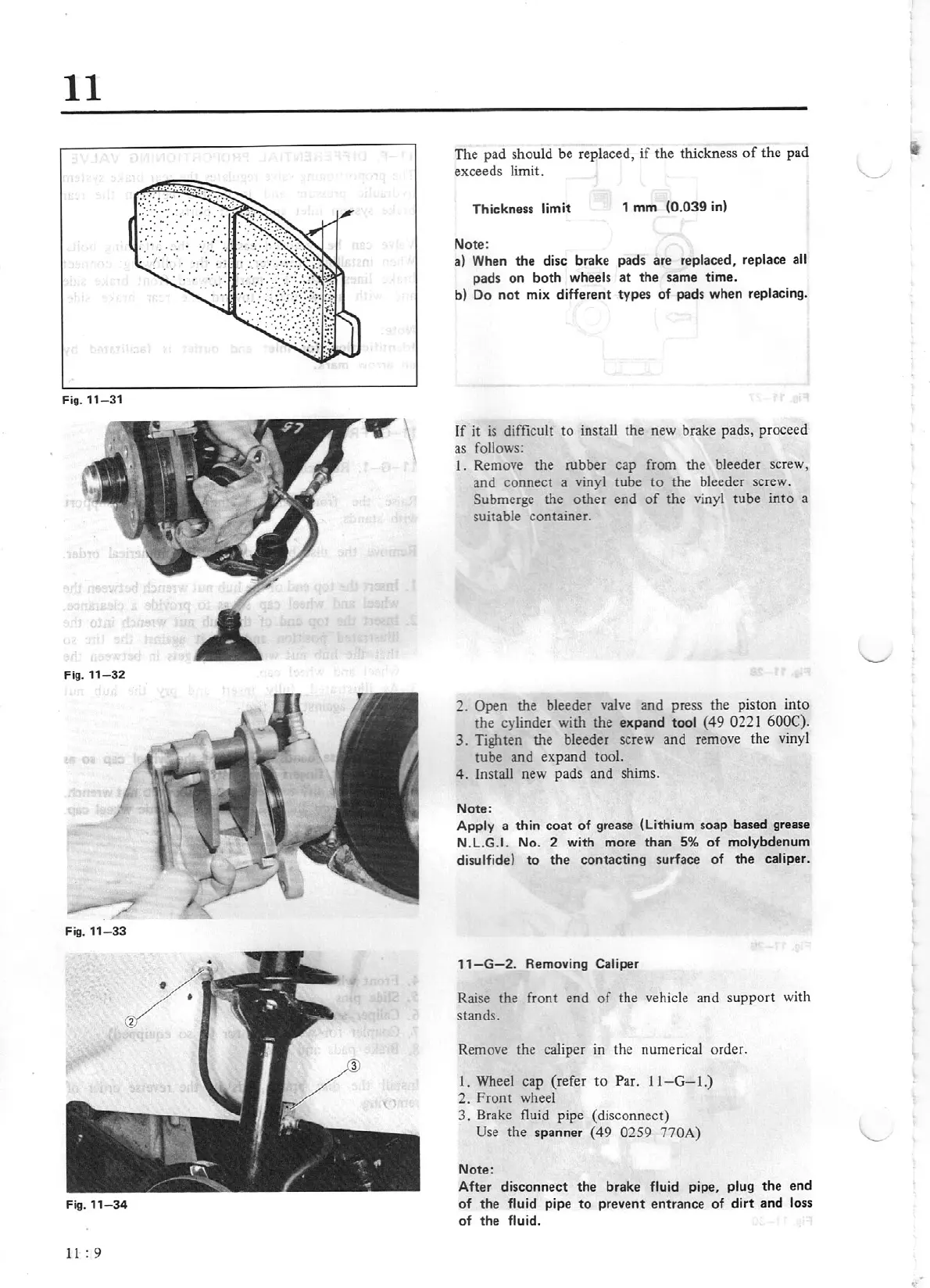
The
pad should
be
replaced,
if
the
thickness
of
the
pad
exceeds limit.
Thickness limit
1
mm
(0.039
in)
Note:
a) When
the
disc brake pads are
replaced,
replace
all
pads
on
both
wheels
at
the same time.
b) Do
not
mix different types
of
pads when replacing.
If
it
is difficult
to
install the new brake pads, proceed
as follows:
1.
Remove the rubber cap from the bleeder screw,
and
connect
a vinyl tube
to
the bleeder screw.
Submerge the
other
end
of
the vinyl
tube
into
a
suitable container.
2.
Open
the bleeder valve and press the piston
into
the cylinder with
the
expand
tool
(49
0221 600C).
3.
Tighten the bleeder screw and remove the vinyl
tube
and
expand
too
l.
4.
Install new pads
and
shims.
Note:
Apply
a thin
coat
of
grease
(lithium
soap based grease
N.L.G.
I.
No.
2
with more
than
5%
of
moly
bd
enum
disulfide)
to
the contacting surface
of
the caliper .
11-G-2.
Removing
Caliper
Raise the front end
of
the vehicle and
suppor
t with
stands.
Remove the caliper in the numerical order.
1.
Wheel
cap
(refer
to
Par.
11-G-I.)
2.
Front
wheel
3.
Brake fluid pipe (disconnect)
Use
the
spanner
(49
0259 770A)
Note:
After disconnect
the
brake
fl
uid pipe,
plug
the
end
of
the
fluid pipe
to
prevent entrance
of
di
rt
and loss
of
the
fluid.