1
Fig. 1- 17
Fig.
1-18
Fig.
1-19
P
iston
Connecting
rod
ipi:lllltl~1
f ig.
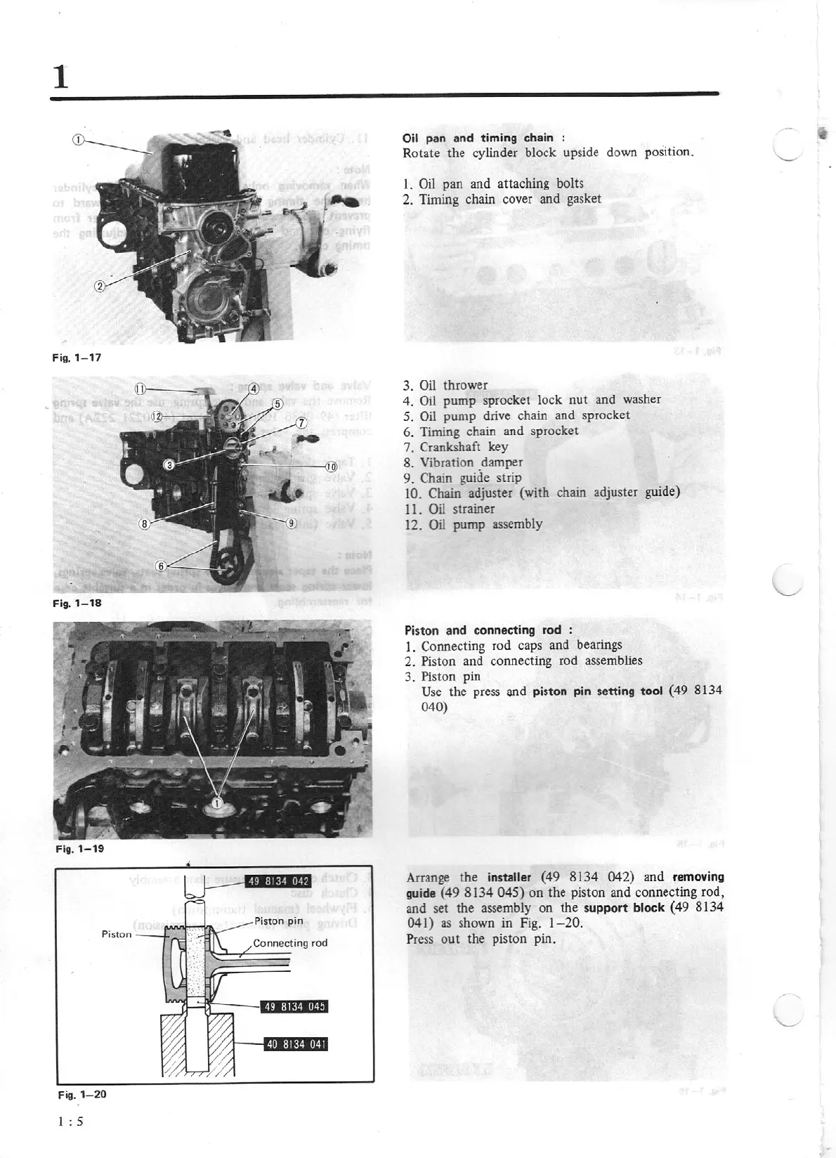
1- 20
I
:
5
Oil
pan and timing chain :
Rotate the cylinder block upside down position.
I.
Oil
pan and attaching bolts
2. Timing chain cover and gasket
3.
Oil
thrower
4.
Oil
pump sprock
et
lock
nut
and washer
5.
Oil
pump drive chain and sprocket
6. Timing chain and sprocket
7.
Crankshaft
key
8. Vibration damper
9.
Chain guide strip
10.
Chain
adjuster (with chain adjuster guide)
11. Oil
strainer
12.
Oil
pump assembly
Pi
st
on
and connecting rod :
l.
Connecting rod caps and bearings
2.
Piston and connecting rod assemblies
3. Piston pin
Use
the pre
ss
and
piston pin setting
tool
(49 81 34
040)
Arrange the
installer
(
49
8134
04
2)
and
removing
guide (49 8134
045)
on the piston and connecting rod,
and set the assembly on the
support
block
(49
81
34
041)
as
shown in Fig.
1- 20.
P
ress
out the piston pin.