lA
Fig.
1A
- 17
Fig.
1A-18
Fig.
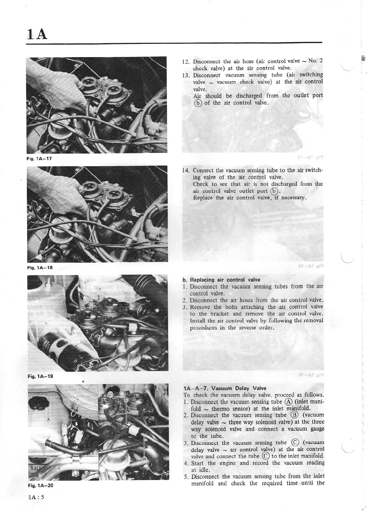
1A-19
•
Fig.1A-20
IA:
5
12. Disconnect the air hose (air control valve
-
No. 2
check valve) at the air control
va
lve.
13. Disconnect vacuum sensing lube (air switching
valve
-
vacuum check valve) at the air control
valve.
Air should be discharged from the
outlet
port
@
of
the air control valve.
14. Connect the vacuum sensing tube
to
the air
switch-
ing valve
of
the air control valve.
Check to see that air
is
not discharged from the
air control valve outlet
port
®.
Replace the air control valve,
if
necessary.
b.
Replacing air
control
valve
l . Disconnect the vacuum sensing tubes from the air
control valve.
2. Disconnect the air hoses from the air control valve.
3. Remove the bolts attaching the
,air control
valve
to
the bracket and remove the air control valve.
Install the air control valve by following the removal
procedures in the reverse order.
1A-
A-7
. Vacuum Delay Valve
To check the vacuum delay valve, proceed
as
follows.
l.
Disconnect the vacuum sensing tube
@
(inlet
mani-
fold
- thermo sensor)
at
the inlet manifold.
2. Disconnect the vacuum sensing tube
@
(vacuum
delay valve
-
three way solenoid valve) at the three
way solenoid valve and connect a vacuum gauge
to the tube.
3. Disconnect the vacuum sensing
tube
©
(vacuum
delay valve
- air
cont
rol valve) at the air
cont
rol
valve
and connect the tube
©to
the inlet manifold.
4.
Start
the engine and record the vacuum reading
at idle.
5.
Disconnect the vacuum sensing tube from the inlet
manifold and check the required time until the