Fig.
lA-66
Fig.
lA-67
. Fig.
1A-69
Vac
ULJ!ll
amplifier
1A
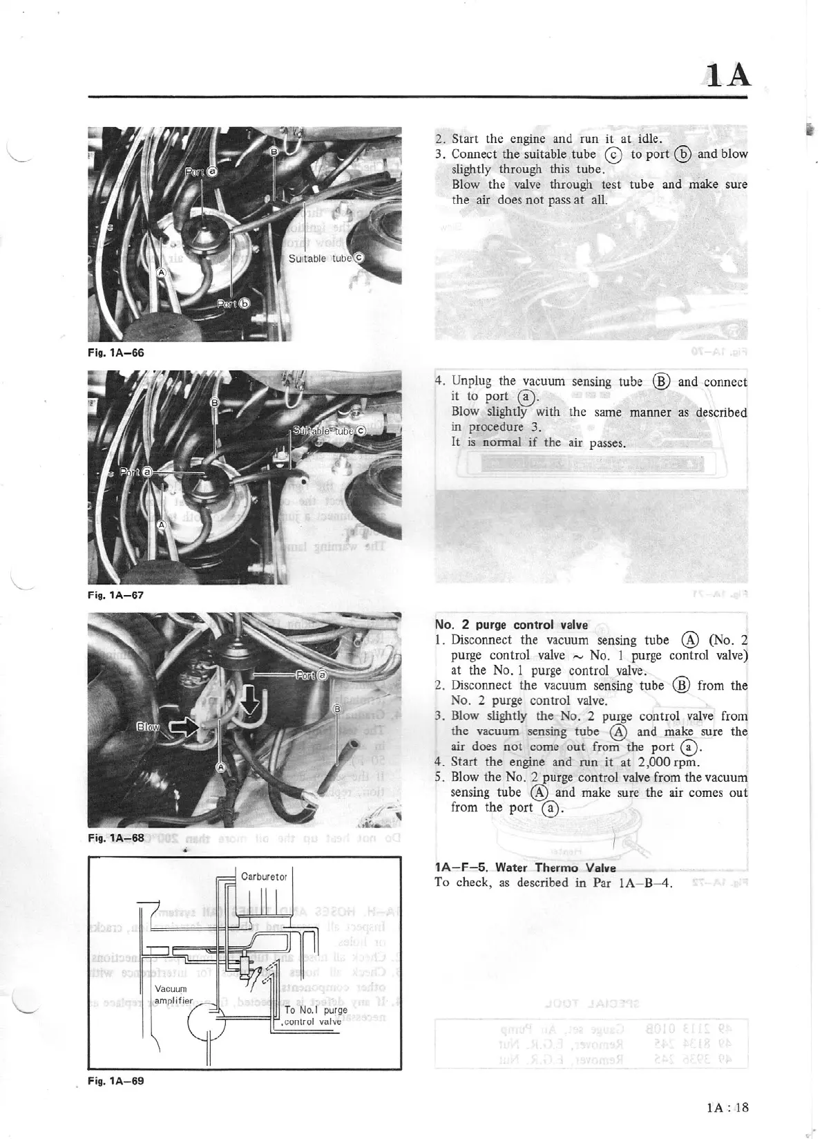
2.
Start the engine and run it at idle.
3. Connect the suitable tube ©
to
port @ and blow
slightly through this tube.
Blow the
valve
through test tube and make sure
the air does not pass at all.
4.
Unplug the vacuum sensing tube @ and connect
it
to port ©·
Blow slightly with the same manner
as
described
in procedure 3.
It
is
normal
if
the air passes.
No. 2
purge
control valve
1. Disconnect the vacuum sensing tube @ (No. 2
purge control
valve
,.._,
No. 1 purge control valve)
at the No. 1 purge control valve.
2. Disconnect the vacuum sensing tube
@ from the
No. 2 purge control valve.
3. Blow slightly the No. 2 purge control valve from
the vacuum sensing tube @ and make sure the
air does
not
come
out
from the
port®·
4.
Start the engine and run
it
at 2,000 rpm.
S.
Blow the No. 2 purge control valve from the vacuum
sensing tube
@ and make sure the air comes out
from the port ©.
1A-
F
-5.
Water
Thermo Valve
To
check,
as
described in Par
lA-B-4
.
lA:
18