IA
Fig. 1A- 62
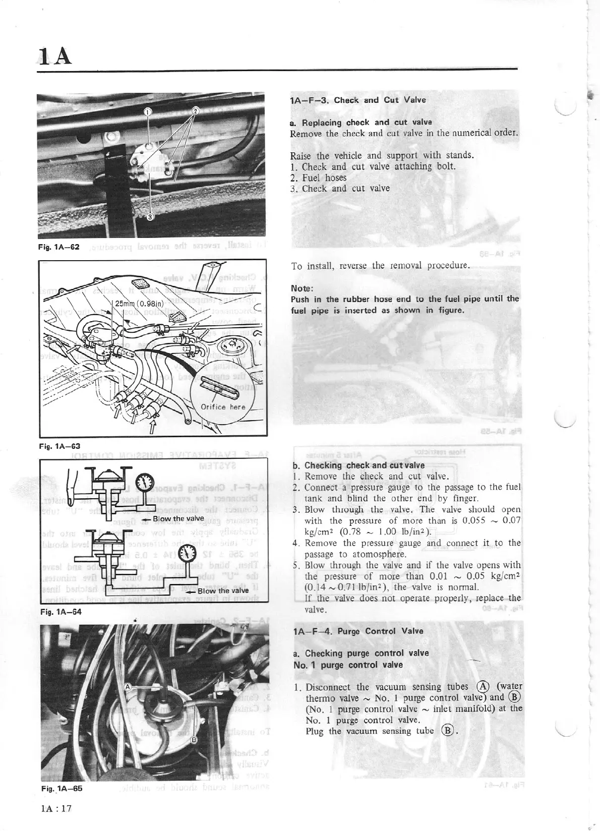
Fig.
1A-63
Fig.1A-64
Fig. 1A-
65
lA:
17
1A-F-3
. Check and
Cut
Valve
a. Replacing
check and
cut
valve
Remove the check and cut valve in the numerical order.
Raise
the
vehicle and s
upport
with stands.
1.
Check
and
cut
valve attaching bolt.
2.
Fuel hoses
3.
Check and
cut
valve
To
install, reverse the removal procedure.
Note:
Push
in
the
rubber hose
end
to
the
fuel
pipe
until
the
fuel pipe
is
inserted as shown
in
figure.
b. Checking check and
cut
valve
I. Remove the check and
cut
valve.
2.
Connect a pressure
ga
uge
to
the passage
to
the fuel
tank
and blind the
ot
her end
by
finger.
3.
Blow through
th
e valve.
The
valve should open
with
th
e pressure
of
more
th
an
is
0.055 - 0.07
kg/cm'l
(0.78
,...,
1.00
lb
/
in
'l
).
4. Remove the pressure gauge and connect it
to
the
passage to atomosphere.
5. Blow through the valve and
if
the
valve
opens with
the pressure
of
more than
O.Ql
,...,
0.
05
kg/cm2
(0.14
,..._,
0.71
lb/in2), the valve is normal.
If
the valve does
not
operate properly, replace
the
valve.
1A-
F-4.
Purge
Control Valve
a. Checking purge
control valve
No. 1 purge
contro
l
va
lv
e
1.
Disconnect the vacuum sensing tubes
(A)
(wa@ter
thermo
valve
- No. 1 purge
cont
rol
valve)
and B
(No. 1 purge control
valve
,...,
inlet manifold)
at
the
No. 1 purge control valve.
Plug
the
va
cuum sensing tube
@.